N93-586-84 Issue 04 AB Page 14 of 32 © Protec Fire Detection plc 2015
5.10 Connecting the Alarm Circuit Wiring
The 3500 has two alarm circuit outputs, each output is rated for continuous use at 400mA and
protected from over-load by an auto resetting thermal ‘fuse’. The ‘fuse’ will reset when the
cause of overload has been removed and the alarm output has been de-activated.
Ensure the alarm circuit wiring conforms to the specifications in section 7.0 of this manual.
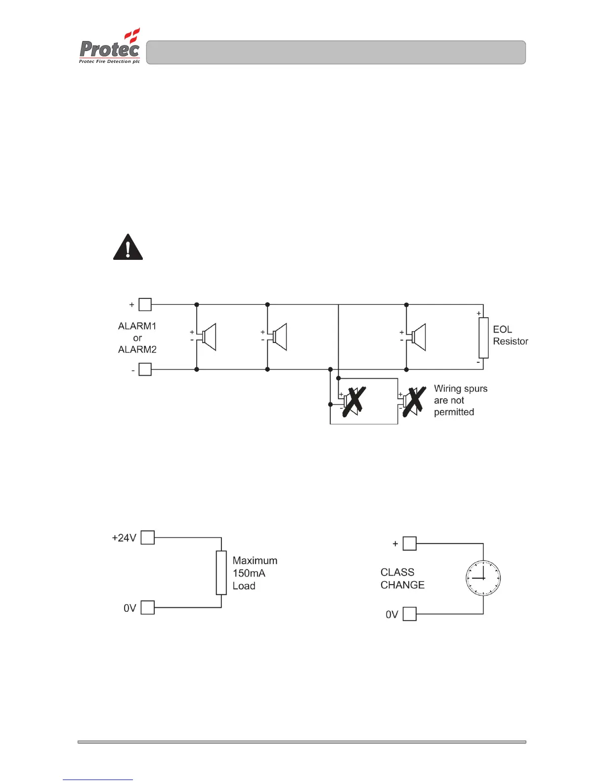
Figure 5.6 shows typical connections for the alarm circuit wiring.
Connect the end of line (EOL) resistor across the terminals of the last device on the alarm circuit.
Wiring spurs must not be connected from the main wiring as the spur WILL NOT be monitored for
open circuit faults.
Only polarised and suppressed sounders can be used on the 3500 alarm circuits.
Failure to use polarised sounders can result in an alarm circuit fault.
All Protec conventional sounder devices are polarised and suppressed as standard.
Figure 5.6 Typical 3500 Alarm Circuit Connection Details
5.11 Connecting the Auxiliary Wiring
The auxiliary wiring comprises the class change input, auxiliary 24V supply output, global fire
contacts and global fault contacts. Note that these connections are optional and if not used do not
require any termination.
Ensure the auxiliary wiring conforms to the specifications in section 7.0 of this manual.
Figure 5.7 Auxiliary Connection Details
Auxiliary 24V Output Connection Class Change Input Wiring