N93-586-84 Issue 04 AB Page 13 of 32 © Protec Fire Detection plc 2015
5.8 Refitting the Control PCB Housing
Ensure that all cable earth connections are sleeved to insulate them and then securely connect them
to the brass earth terminals in the back-box.
Carefully route the battery leads (from the rear of the control PCB housing) down between the two
batteries.
If the 3500 is equipped with a fire brigade panel controller, ensure the ribbon cable connected to the
back of the control PCB housing is located over the top of the control PCB housing when refitting
into the back-box.
Replace the control PCB housing (a reversal of removal), ensuring it is pushed flush to the back-box
and that the battery leads do not get trapped. Secure with the four screws removed previously,
taking care not to over tighten the screws.
5.9 Connecting the Detection Zone Wiring
Ensure the detection circuit wiring conforms to the specifications in section 7.0 of this manual.
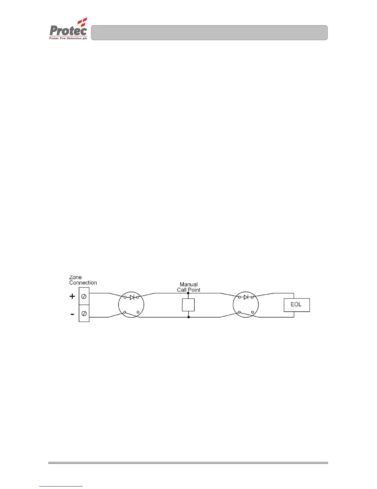
Figure 5.5 shows typical connections for the detection zone wiring.
Connect the end of line (EOL) device (resistor or capacitor depending on requirements) across the
terminals of the last device on the zone circuit.
Wiring spurs must not be connected from the main zone wiring as the spur WILL NOT be monitored
for open circuit faults.
To ensure compliance with BS5839 part 1 each detector base must include a series low voltage drop
diode. This ensures that Manual Call Points following a removed detector still function correctly.
Protec 3000PLUS/BASE and 3000PLUS/FFBASE products incorporate the diode as standard.
Figure 5.5 Typical 3500 Detection Zone Connection