N93-586-84 Issue 04 AB Page 10 of 32 © Protec Fire Detection plc 2015
5.4 Removal of the Control PCB Housing
Before handling the 3500 panel control PCB housing it is important that any
operatives discharge themselves of any static charge that may have built up. This can
be done by momentarily touching a solid earth point (a non-painted part of a radiator,
for example).
The Control PCB housing is a sealed unit and must not be opened. Tampering with
this unit will invalidate the warranty. If the unit becomes faulty it must be returned for
repair.
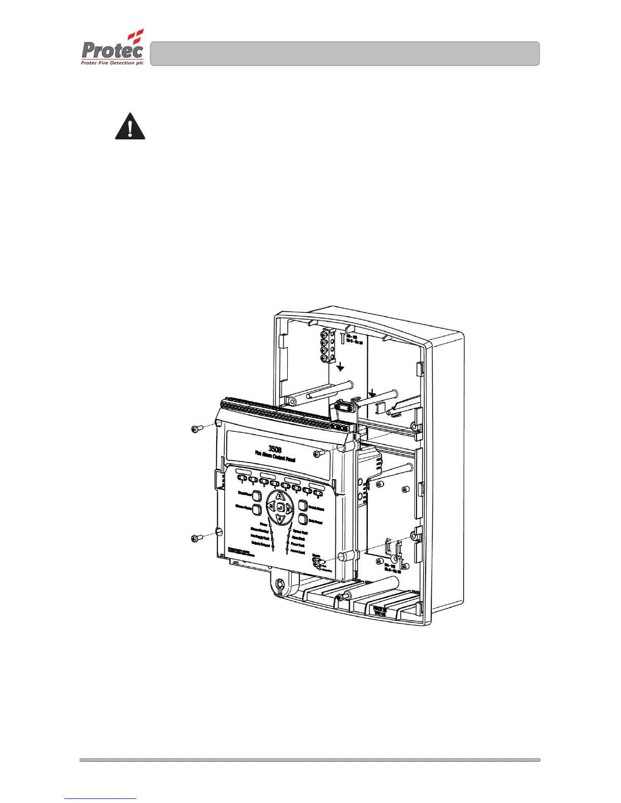
Unscrew and remove the four mounting screws on the control PCB housing. Carefully lift away the
control PCB housing from the plastic enclosure. See figure 5.2.
The 3500 control PCB housing and all screws should be stored in the cardboard carton away from
the place of work where they will not get damaged.
Figure 5.2 Removal of the 3500 Control PCB Housing