N93-586-84 Issue 04 AB Page 15 of 32 © Protec Fire Detection plc 2015
5.12 Connecting the 3500 Repeat Panel
The 3500 can support additional repeat panels allowing the state of the system to be monitored from
alternative locations. The 3500 control panel can support up to 5 3500 repeat panels, supplied from
the auxiliary 24V supply output or up to 10 3500 repeat panels, supplied from an external EN54-4
power supply unit. The connections for the repeat panel are optional and if not used do not require
any termination.
The 3500 repeat panel is mounted using the same process followed for mounting a 3500 control
panel.
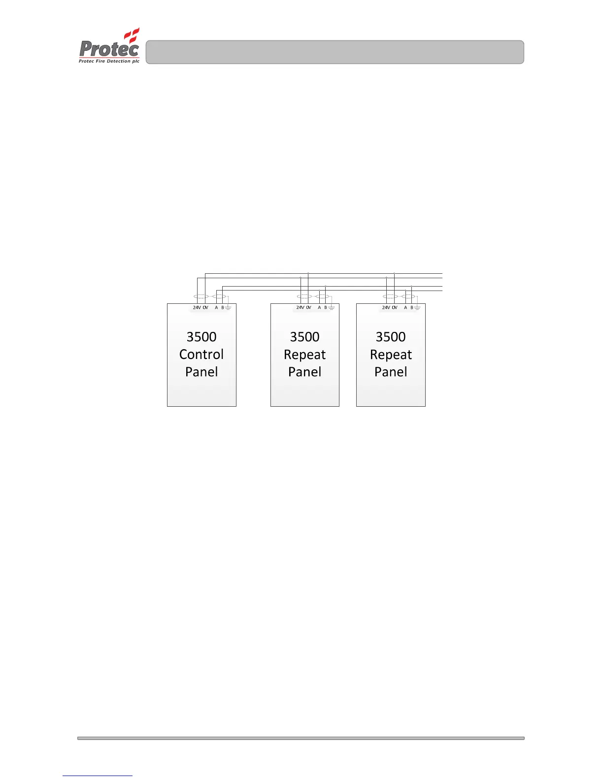
Ensure that the correct polarity is observed when wiring the 24V supply to the 3500 repeat panel.
The RS485 is connected from the A terminal of the host panel to the A terminal of the repeat panel
and the B terminal of the host panel to the B terminal of the repeat panel.
The connections are shown in figure 5.8
Figure 5.8 Typical wiring diagram
When carrying out commissioning of the 3500 control panel ensure that the 3500 repeat panels
mimic the display of the 3500. Ensure that if the if the repeat panel is locally muted, the buzzer
resounds upon the activation of an additional fault or fire.
For further details regarding a 3500 repeat panel refer to DEL2129, supplied with the unit.
To further
repeat panels