EasyManua.ls Logo

Protec 3500 - Appendix 1 List of 3500 Spares and Accessories; Appendix 1; 3500 Controls, Indications and Connections

Protec 3500
32 pages
Print Icon
To Next Page IconTo Next Page
To Previous Page IconTo Previous Page
Loading...
N93-586-84 Issue 04 AB Page 28 of 32 © Protec Fire Detection plc 2015
Appendix 1 List of 3500 Spares and Accessories
Description Protec Stock Code
Standby battery inter connection lead N 41-796-44
12V 3.3Ah VRLA battery (Online OL3.3-12) N 13-120-24
3500 8 zone spares kit N 62-807-SPARES
3500 user manual N 93-571-87
3500 Installation & commissioning manual (this manual) N 93-586-84
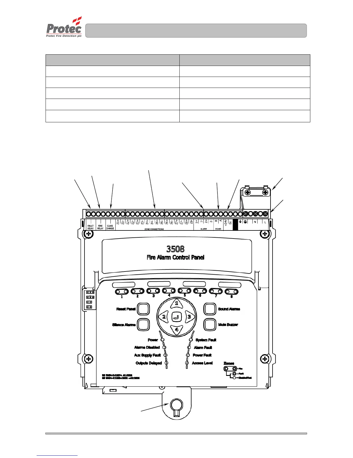
Appendix 2 3500 Controls, Indications and Connections
The diagram below shows the 3500 Control PCB housing and highlights the main connections and controls.
ac mains input
supply connections
Monitored
Auxiliary 24V
output
Monitored
conventional
alarm outputs
Class Change
input
Global fire
contacts
Global fault
contacts
Mains cable
restraint
Detection zones
RS485
Communications
Firemans access level 2 keyswitch input
(Specific models only)
1
2
3
4
Configuration
links
www.acornfiresecurity.com

Table of Contents

Other manuals for Protec 3500

Related product manuals