N93-586-84 Issue 04 AB Page 25 of 32 © Protec Fire Detection plc 2015
6.12 Configuring the Volt Free Contact Normal State
The quiescent state of the 3500 Volt free contacts may be configured to be 'Normally Open' or 'Normally
Closed'. Table 6.0 shows how setting the configuration links changes the operation.
The Volt free contact configuration is setup by setting the front panel configuration links as follows.
Sequence Effect
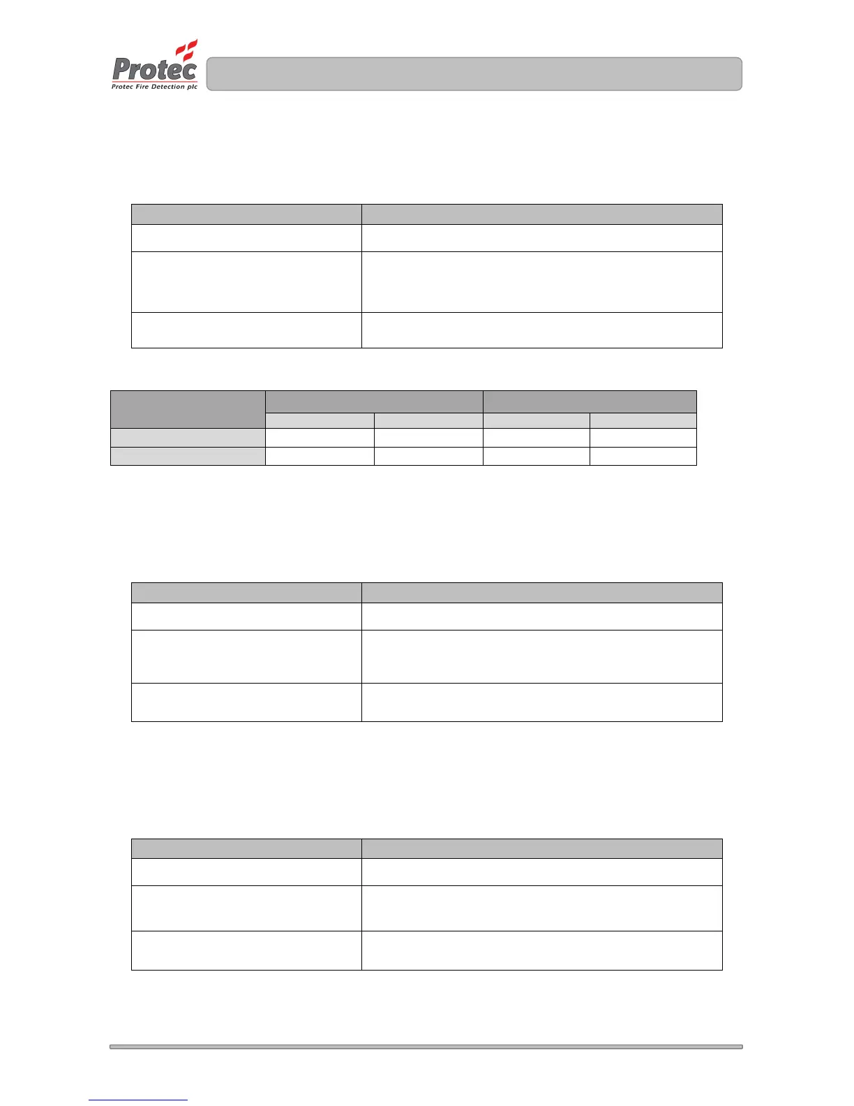
Remove panel door (see section 5.2) Reveals configuration link aperture (see figure 5.0)
Using an appropriate tool alter
jumper 1 or 2 (see figure 5.0)
Jumper 1 or 2 in ‘ON’ position to configure normally closed
contacts
Jumper 1 or 2 in ‘OFF’ position to configure normally open
contacts
Replace panel door (see section
5.12)
Hides configuration link aperture
Table 6.0 Aux fault contact state configuration
Jumper Link Configuration
Global Fire Contacts (Link J2) Global Fault Contacts (Link J1)
In Fire Not In Fire In Fault Not in Fault
Normally Open
Short Circuit Open Circuit Short Circuit Open Circuit
Normally Closed
Open Circuit Short Circuit Open Circuit Short Circuit
6.13 Configuring Alarm Output Trigger Source
The 3500 can be configured to activate the alarm outputs differently depending on the type of zone trigger
(manual or automatic).
The settings are changed by altering the jumper link configuration as follows.
Sequence Effect
Remove panel door (see section 5.2) Reveals configuration link aperture (see figure 5.0)
Using an appropriate tool alter
jumper 3 (see figure 5.0)
Jumper 3 in ‘ON’ position to configure global activations
Jumper 3 in ‘OFF’ position to configure separate automatic
and manual activations
Replace panel door (see section
5.12)
Hides configuration link aperture
6.14 Configuring the Detection Circuit End of Line Type
The 3500 can accommodate resistive or capacitive end of line (EOL) termination. This applies to all zones of
the panel, and cannot be configured on a zone by zone basis.
The EOL type is setup by setting the front panel configuration links as follows.
Sequence Effect
Remove panel door (see section 5.2) Reveals configuration link aperture (see figure 5.0)
Using an appropriate tool alter
jumper 4 (see figure 5.0)
Jumper 4 in ‘ON’ position to configure capacitive EOL
Jumper 4 in ‘OFF’ position to configure resistive EOL
Replace panel door (see section
5.12)
Hides configuration link aperture