N93-586-84 Issue 04 AB Page 17 of 32 © Protec Fire Detection plc 2015
5.14 Connecting the Fire Brigade Panel Controller
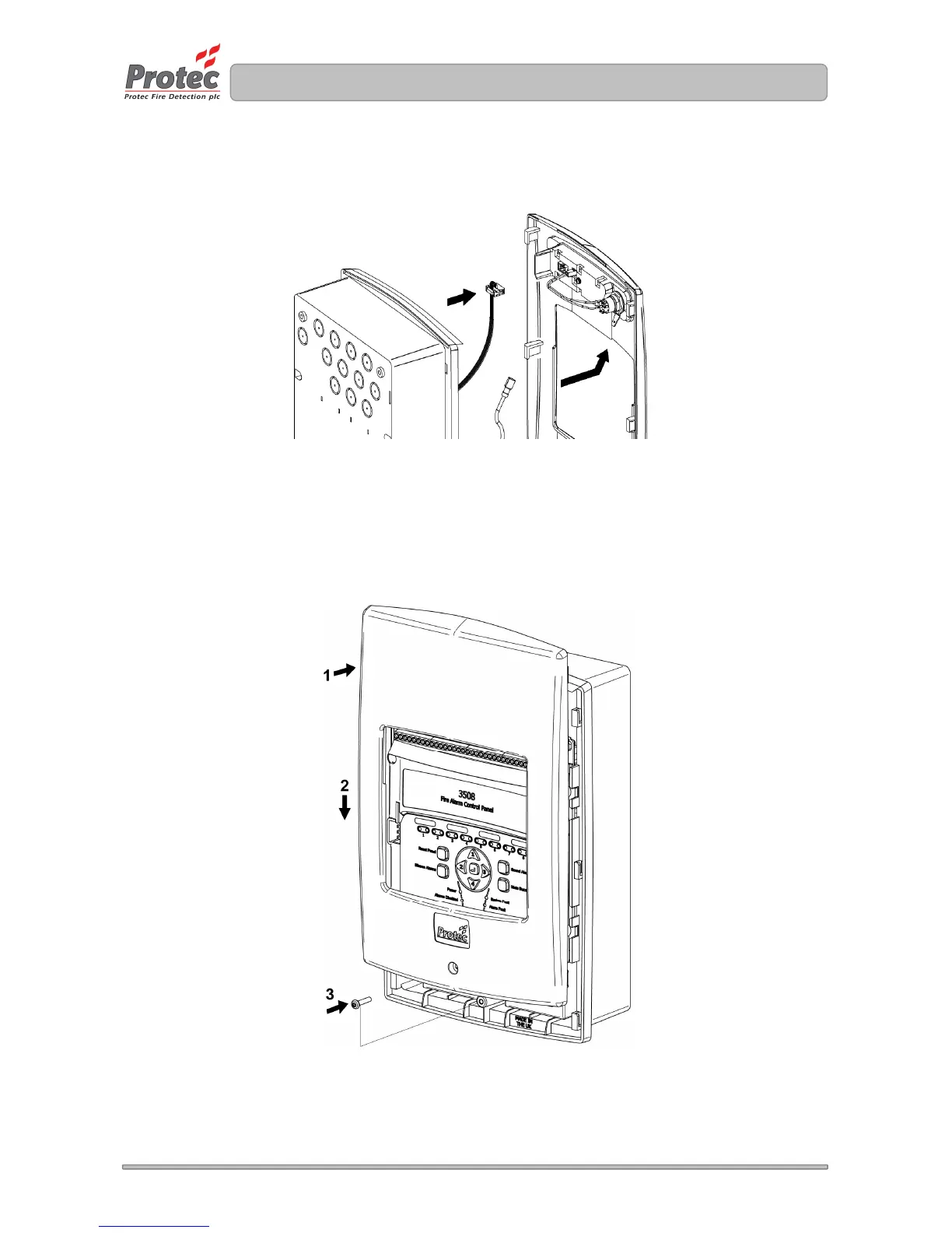
If the 3500 is equipped with the optional fire brigade controller ensure that the ribbon cable and earth
lead are re-connected to the rear of the controller as shown in figure 5.11.
Figure 5.11 Reconnecting the Fire Brigade Panel Controller
5.15 Re-fitting the Door
Before replacing the door ensure all mains, zone, alarm and auxiliary wiring has been completed and
will not foul the door when it is refitted.
Replace the plastic door by raising the door and placing flush to the back-box of the panel (figure
5.12 step 1). Slide the door down and ensure it pushes fully home into the back-box (figure 5.12 step
2). Finally screw in the fixing screw, taking care not to over tighten the screw (figure 5.12 step 3)
Figure 5.12 Refitting the 3500 door
5.16 Switching the Mains Power On
Switch the fused isolator to the ‘ON’ position.
The green ‘Power’ indicator will illuminate, the 3500 is now ready to be programmed and
commissioned.