PRO-VISION® Video Systems
38 provisionusa.com
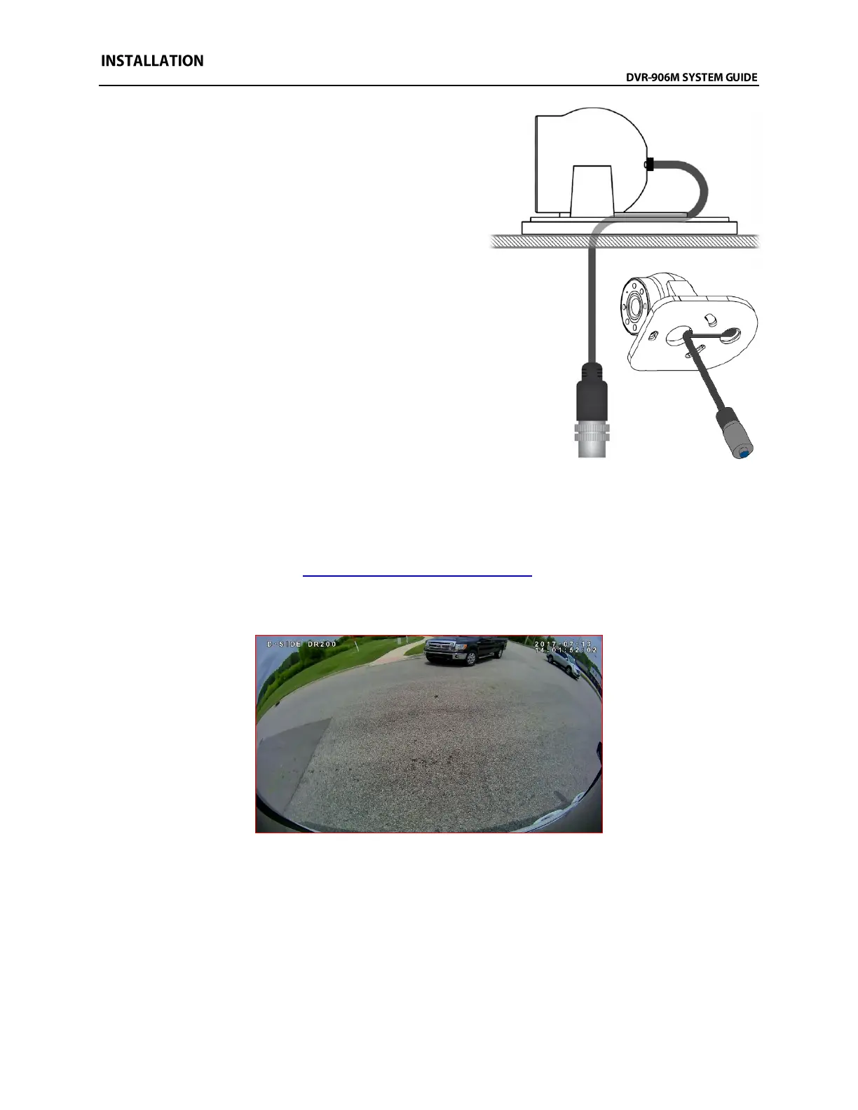
15. If you are certain of the cameras mounting location
and that the correct hole for the cable has been
drilled, then attach the gasket to the camera base,
route the camera cable through the base and
gasket, and then through the 5/8” hole and hold the
camera in its mounting location. The camera cable
should make an “S” shape as it travels out the back
of the dome ball, through the hole in the base, then
back through the hole drilled in the mounting
surface under the dome ball.
16. Use the mounting hardware provided to attach the
camera base to the mounting location. Check
behind the mounting surface to ensure the
hardware has clearance. DO NOT completely
tighten hardware yet.
17. Place the dome ball into its socket in the camera
base and ensure there is enough camera cable to
move the camera ball, but not too much. Feed any
additional camera cable slack back behind the
mounting hole/surface and then tighten mounting hardware.
18. Attach the camera cover to the camera with the three (3) Allen head mounting screws. Leave the
screws slightly loose until the camera is aimed.
19. Power on the DVR unit and connect to the Wi-Fi to view the live camera image to properly aim it
on the view page. (See Viewing Cameras on a Smart Device for connection details)
20. After the camera is aimed, tighten the three (3) Allen head mounting screws to lock the camera
aim.
Example view of driver’s side of delivery van