Connecting the controller
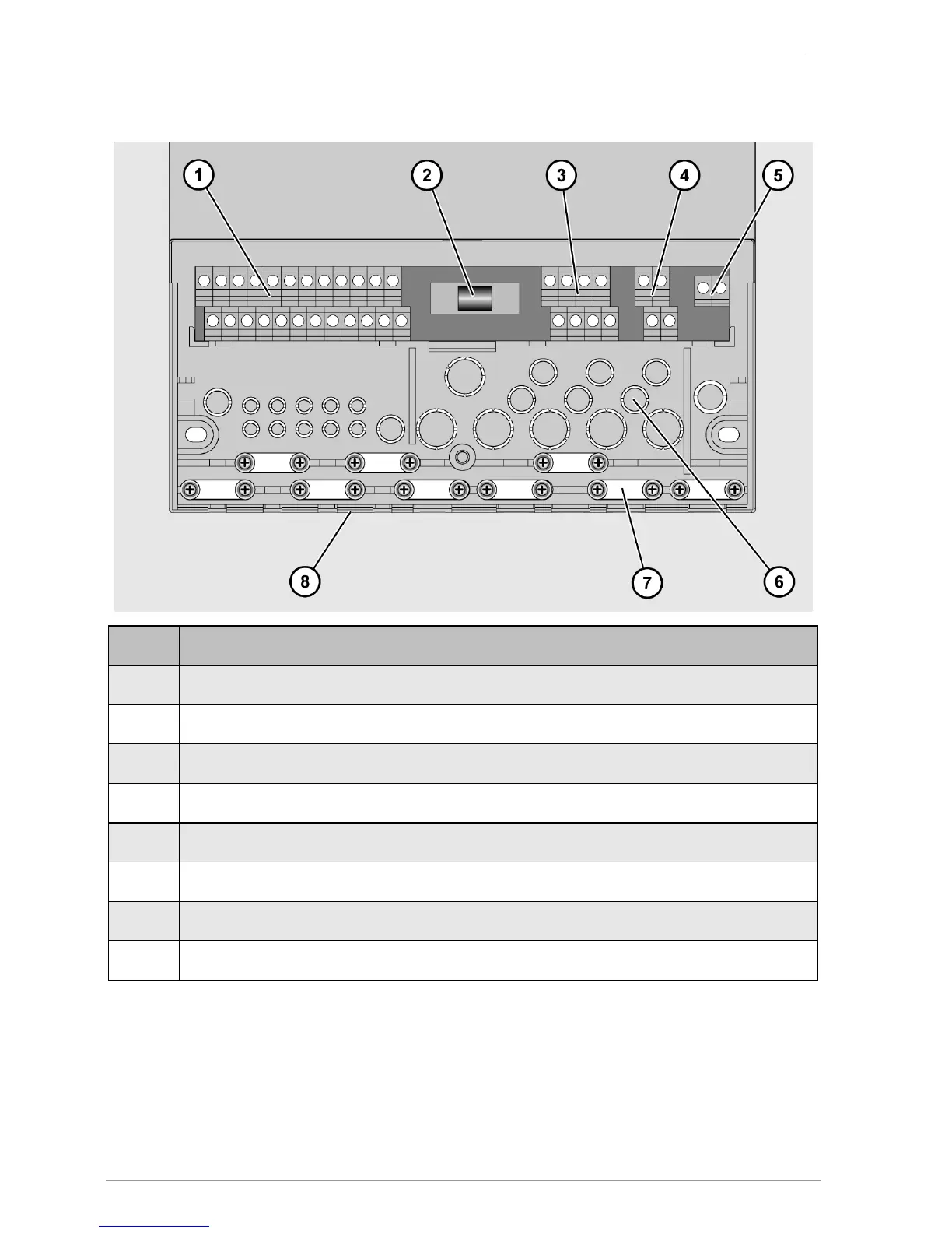
The following illustration shows the elements of the controller that are important for
connection:
1 Terminals for extra-low voltage area
3
Terminals for 230 V area
4 Terminals for protective conductor
5
Terminals for relay contact
6
Cut-out apertures for cable feedthrough at the back
7 Screw clamps for securing the cables
8
Cut-out apertures for cable feedthrough on the underside
Connect the cables to the corresponding terminals.
Information about connecting the system components to the corresponding terminals can
be found in the section Assignment of the terminals to the system components from page 15
onwards.
Screw the terminal cover securely back in place.
 Loading...