Controlling HE pumps with analog signals
In the case of the pump control system complete with analog signal, the controller sends a
0–10 V analog signal to terminals HE1 and HE2.
Definitions for the output voltage (U):
• Pump off: 0.5 V < U < 1.0 V
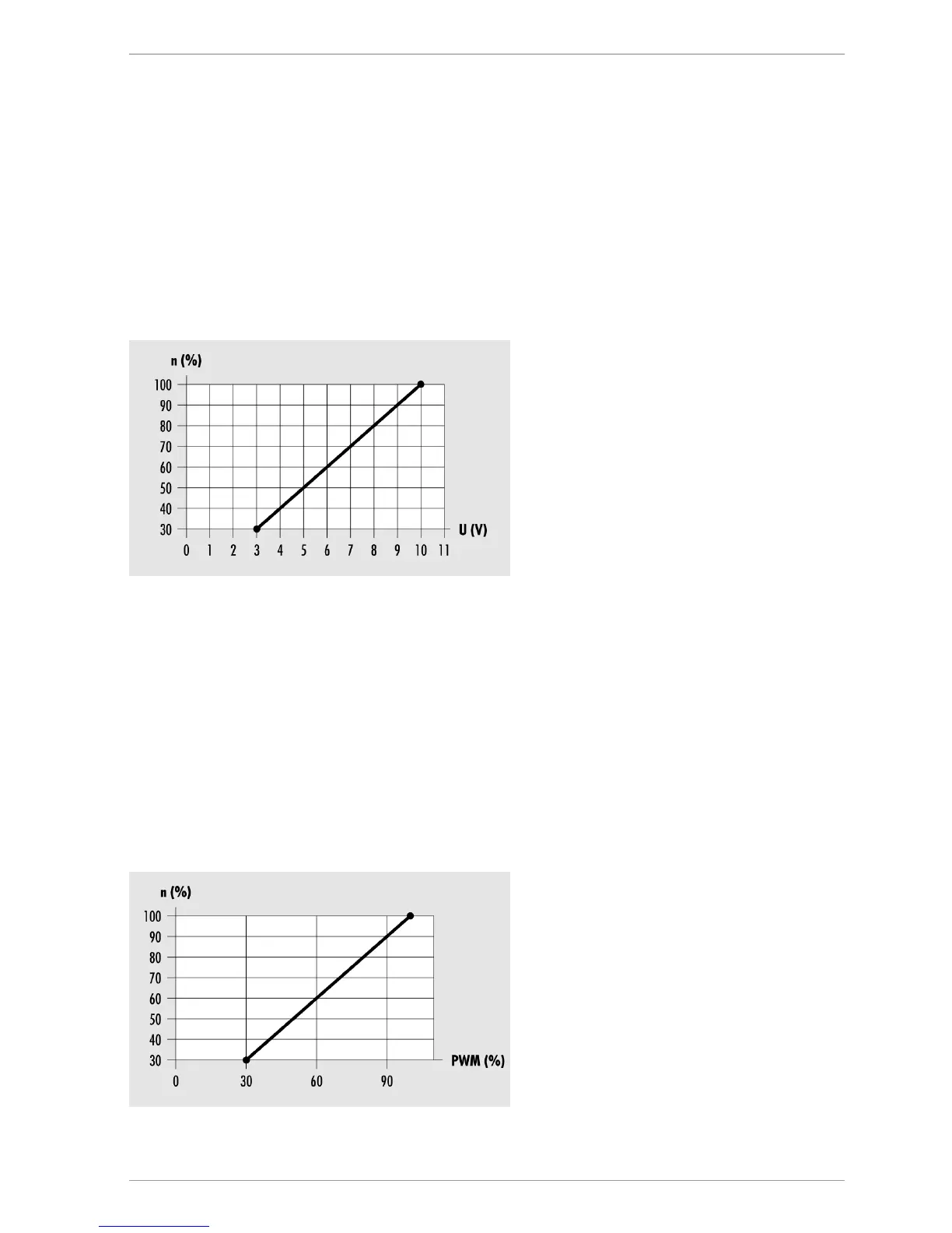
• Speed control: Linear characteristic 3 V < U < 10 V (for a minimum pump output of 30
%)
The following diagram shows the power curve for the pump control system with analog
signal.
n (%) – Pump output U
(V) – Output voltage
Controlling HE pumps with PWM signals
In the case of the pump control system with PWM signal, the controller sends a PWM signal
(pulse width modulation signal) to terminals HE1 and HE2. The PWM signal can be sent
normally (not inverted) or inverted.
Not inverted
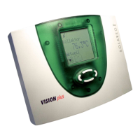
In the case of the pump control system with a non-inverted PWM signal, the nominal speed
of the pump (0–100 %) corresponds to the PWM signal (0–100 %). The following diagram
shows the power curve for the pump control system with a non-inverted PWM signal.
n (%) – nominal speed of the pump
PWM (%) – non-inverted PWM signal