Close
2)
with torque /
Open
2)
with required rotation angle
Set value range: 0-10 V / 0-20 mA
Set value range: 2-10 V / 4-20 mA
Set value / Split-Range 5-10 V/10-20 mA
Set value / Split-Range 6-10 V/12-20 mA
Set value / Split-Range 0-5 V/0-10 mA
Set value / Split-Range 2-6 V/4-12 mA
Torque end position with counterclockwise rotating
valve shaft (CCW)
Torque end position with clockwise rotating valve
shaft (CW)
Valve curve LINEAR setpoint/position
Valve curve QUICK OPENING Setpoint/position
1)
After changing the switches S2-3, S2-4 and S2-, perform re-calibration to activate the new operating mode!
2)
„Close“ = Clockwise (CW), „Open“ = Counter Clockwise (CCW)
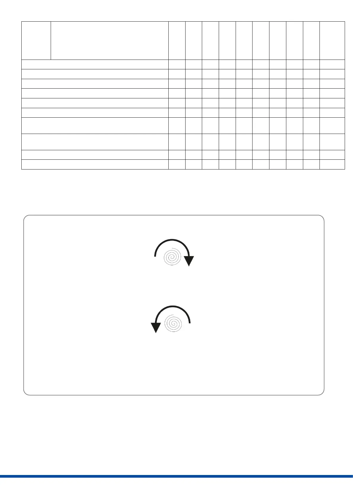
7.2 Operating direction
Clockwise (CW) = Spring drives output valve shaft clockwise
Counter Clockwise (CCW) = Spring drives output valve shaft counterclockwise
Figure 7: Operating direction
Actuator CW
Spring drives output valve shaft CW
DIP switch S2.1 Off Travel end position Torque end position
DIP switch S2.1 On Torque end position Travel end position
Actuator CCW
Spring drives output valve shaft CCW
DIP switch S2.1 Off Travel end position Torque end position
DIP switch S2.1 On Torque end position Travel end position
 Loading...