- One of 18 AWG, 2-conductor, shielded cable coming from
the intercom base station if intercoms are being used.
- 1 of RG59U video cable if a pinhole camera is being used.
- One of 18 AWG, 2-conductor cable for the presence sensor
if it is being used.
4
Strip back the outer insulation and shield foil from both of
the 18 AWG, 4-conductor, shielded cables (coming from the
controller or previous AI device in line and going out to the next
AI device in line), being careful not to cut the bare shield wire.
Strip ¼ inch of insulation off the end of each of the individual
colored conductor wires.
5
Remove the terminal blocks from the keypad circuit board by
sliding them up and off.
6
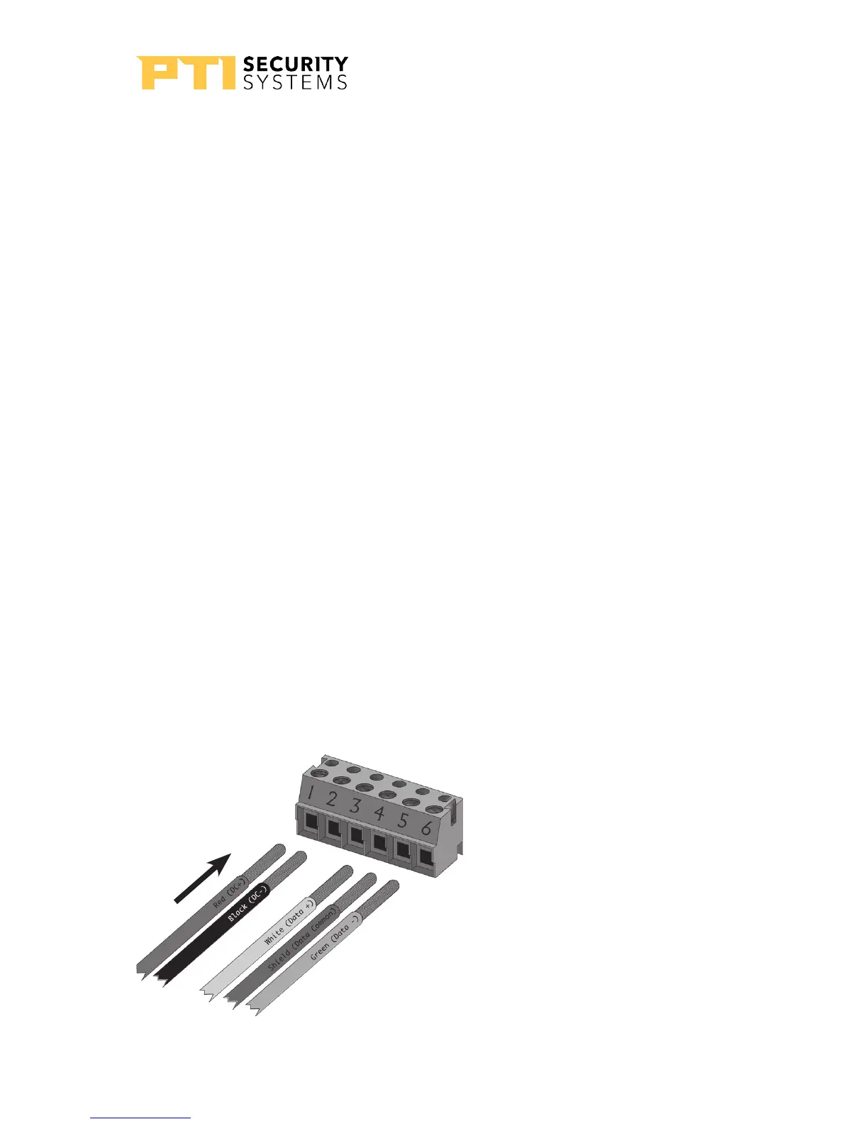
For Terminal Block P1 “Drawing 11: Terminal block
P1 wiring” on page 13 Insert both red wires (coming in
from the controller and going out to the next AI device) into
terminal slot 1 on the first terminal block (P1).
Terminal Block P1 (Left)
1. Red DC + *
2. Black DC – (see footnote)
3. Earth Ground (if applicable)
4. White Data +
5. Shield**
6. Green Data –
* If using AC power, place the AC
wires in slots 1 and 2. We recommend
12-18VAC or DC can be used.
** Shield wire should be insulated with
heat shrink or electrical tape.
Drawing 11: Terminal block P1 wiring
APEX Access Device
13
rev. 7-2017 114A3863.E