7
Ensure that both wires are seated all the way inside the slot.
Use a flathead precision screwdriver to tighten down the
terminal screw.
8
Verify that the terminal slot has tightened down on the copper
wire and not on the rubber insulation. There should be no
copper wire showing outside of the terminal slot. Gently tug
the wires to verify that they are tightly held inside the terminal
slot.
9
Repeat this process with each of the remaining wire connections
as shown in “Drawing 11: Terminal block P1 wiring” on page
13. Insert both black wires into terminal slot 2 on P1.
Ensure that both wires are seated all the way inside the slot.
10
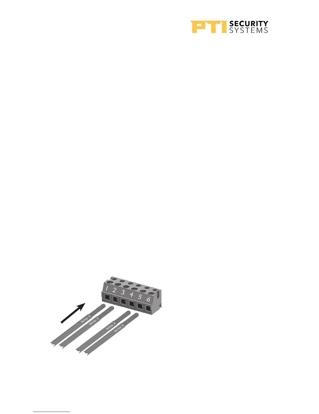
For terminal block p4 “Drawing 12: Terminal block P4
wiring” on page 14 The right (relay) terminal block is used
for the relay connections. Pins 1, 2, and 3 are for the rst
relay and Pins 4, 5, and 6 are for the second.
Terminal Block P4 (Right)
1. Relay 1 Normally Open Wire
2. Relay 1 Common Wire
3. Relay 1 Normally Closed Wire
4. Relay 2 Normally Open Wire
5. Relay 2 Common Wire
6. Relay 2 Normally Closed Wire
Drawing 12: Terminal block P4 wiring
APEX Access Device
14
114A3863.E rev. 7-2017