49
ESC
6. MENUS
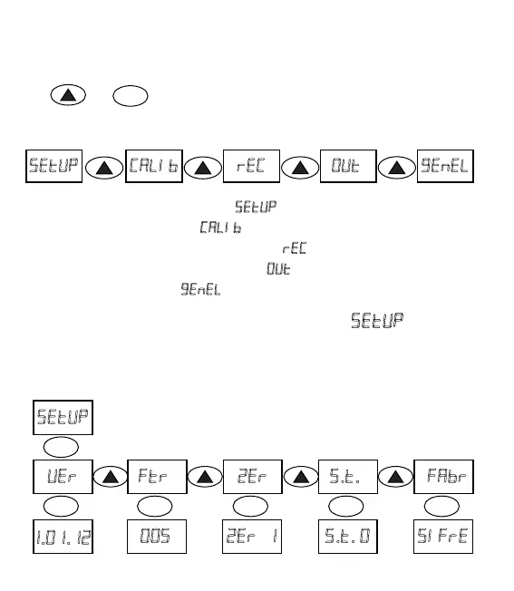
a. PARAMETER INPUT MENU ()
• Parameter Input Menu ( )
• Calibraon Menu (
)
• Transistor Programming Menu (
)
• Output Configuraon Menu (
)
• General Menu (
)
To enter the programming page, aer weight info appears on the screen, click
keys and at the same me. You can follow the below operang chart
for selecon of menu to be adjusted. (* It may vary as to the opons)
ENT
ENT ENT ENT ENT ENT
..
..
..
Digital
Filter
Factory
Sengs
Tare Keys
Open/Close
Zero
Follow
This is the page where user can learn the version number of the device, enter
the filter value, acvate the Zero Tracking feature, enable the tare funcon
over the keypad, factory sengs can be restored.
e. WARNINGS!!!
1. Read the user’s manual before starng the device.
2. Work on the device must be carried out by a qualified electrical engineer. Usage
of the device by an unqualified person might result in undesired damages.
3. Do not remove any connected cables and connectors from the device while it is
working.
4. Check the 24VDC Voltage and earth connecons before starng PD-20S
transmier.
5. Do not give a start to PD-20S before making loadcell connecons.
6. Connect the screen (shield) terminal of the loadcell cable, connecon with the
device, to earth. As the signals coming from Loadcell are at mV level, signals can be
effected by noise when cable is not properly grounded.
7. Make the calibraon, PD-20S must have been started first and loadcell wiring
already been done, aer the display shis towards plus when pressed on the scale.
8. Before making the calibraon, make sure that Loadcell Capacity Value, Factor
Value, Sensivity Value are correctly entered.
9. Total resistance of loadcells connected to transmier must be no lover than 85 Ω.
For Instance: 4 pcs of 350 Ω or 8 pcs of 700ohm loadcells can be connected.
10. In MODBUS communicaon, when more than one device is used, terminang
resistor of 120 Ω 1W value shall be connected to communicaon port of latest
installed device.