ENGLISH
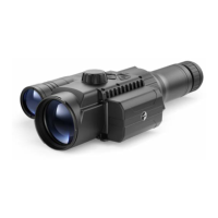
Mounting a monocular on the digital module
The Pulsar 5x30 monocular (included in the package) enables you to transform
a digital module into a digital vision device for night-time observation with a
magnication of 5x.
• Insert the monocular
tightly into the digital
module as far as it will
go so that the pins on
the monocular body (E)
t into the slots (D) of the
digital module (see Fig.).
• Turn the monocular
anticlockwise so that the monocular
is xed onto the digital module. The
triangular mark on the digital module and the
square on the monocular body must be aligned.
• To remove the monocular, turn it clockwise and gently
pull it towards you.
Mounting the digital module on an optical device
• Select the adapter (available separately) with the required diameter of insert
depending on the outer diameter of the lens of your optical sight (see the
Table).
• The designation 42mm / 50mm / 56mm in the title of the adapter refers to
the optical diameter of the lens in the optical sight.
• Remove the cap (16) from the 42mm adapter (19) (#79171) by turning it
clockwise. To remove the cap from the 50mm (#79172) or 56mm (#79173)
adapters, turn it anticlockwise.
• Degreasing of the lens body of the device before mounting is recommended.
• Mount the insert (18) onto the adapter (19) as far as it will go.
• Mount the adapter with the insert into the lens of the optical device (17).
• Move the lever (22) from its initial OPEN position to the CLOSE position.
• Ensure that the adapter ts snugly against the lens.
• If there is any gap, do the following:
– Loosen the locking screw (20) with an Allen key (S=2mm).
– Tighten the screw (21) with an Allen key (S=4mm) with the force necessary
to ensure that the adapter ts tightly against the lens. The clamping forces
should be 1 Nm.
– Tighten the locking screw (20).
• The effort can be tested with a torque screwdriver.
• Insert the digital module rmly into the adapter so that the pins located
in the adapter case t into the grooves (23) of the digital module. Turn the
digital module clockwise as far as it will go. The triangular mark on the
digital module and the square on the adapter body must be aligned.
• Turn the digital module handle (22) to the OPEN position and align the
digital module with the horizon.
5

 Loading...