8
Programed for ‘Set Area’: one or more
areas will be set when pressed.
Programed for ‘Unset Area’: one or more
areas will be unset when pressed.
Programed for ‘User Output’. For example;
a gate can open or close at a button press.
Programed for ‘Status LED’. This displays the
system status when pressed:
Using the Keyfob (If you have a Wireless ZEM ):
Locking the keyfob:
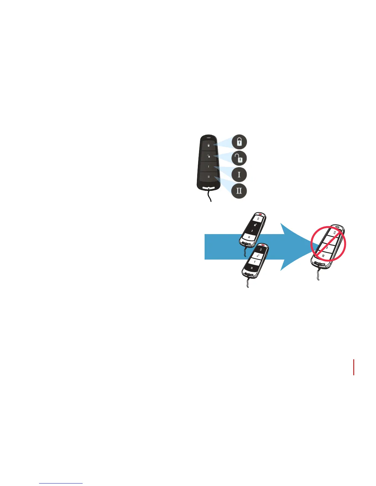
All four buttons on the keyfob can be ‘locked’ to prevent you from
accidentally pressing them. You can do this by pressing the two
central keys together ( >& I ) or the two outer keys together
( & II ).
As indicated on the diagram to the right. A RED LED will ash to
indicate that the fob has been locked. To unlock the keyfob press
the same two keys together again and a GREEN LED will ash
to indicate that it is now unlocked. Please note that locking the
keyfob disables all LED indications.
RED = Set
GREEN = Unset
AMBER = Fault
Quick Setting:
If you have chosen to program one of the keyfob buttons as ‘Set Area’, you can then opt to ‘quick set’ that area. When you press
the button to set the area, the EURO 46 APP panel will begin to count down your exit time (depending on what exit mode
has been programed by your engineer). Once this ‘setting stage’ begins, press the same button on the keyfob again and the
system will set immediately.
The unset LED on the Control Panel will turn o and a beep will sound to signal that the system has been set. The RED LED on
the keyfob will illuminate for a short time to conrm this.
The wireless keyfob has four buttons that can be
programed to perform specic functions: no action, show
status, set area, unset area, latch output, timed output and
HU alarm activation. This can be customised to operate as
desired (programed in the function ‘Change Codes’). The
keyfob diagram on the right shows how each button can
be programed:
Press outer
keys together
or inner keys
together:
The LED will
light up RED
and the keys
will lock.

 Loading...