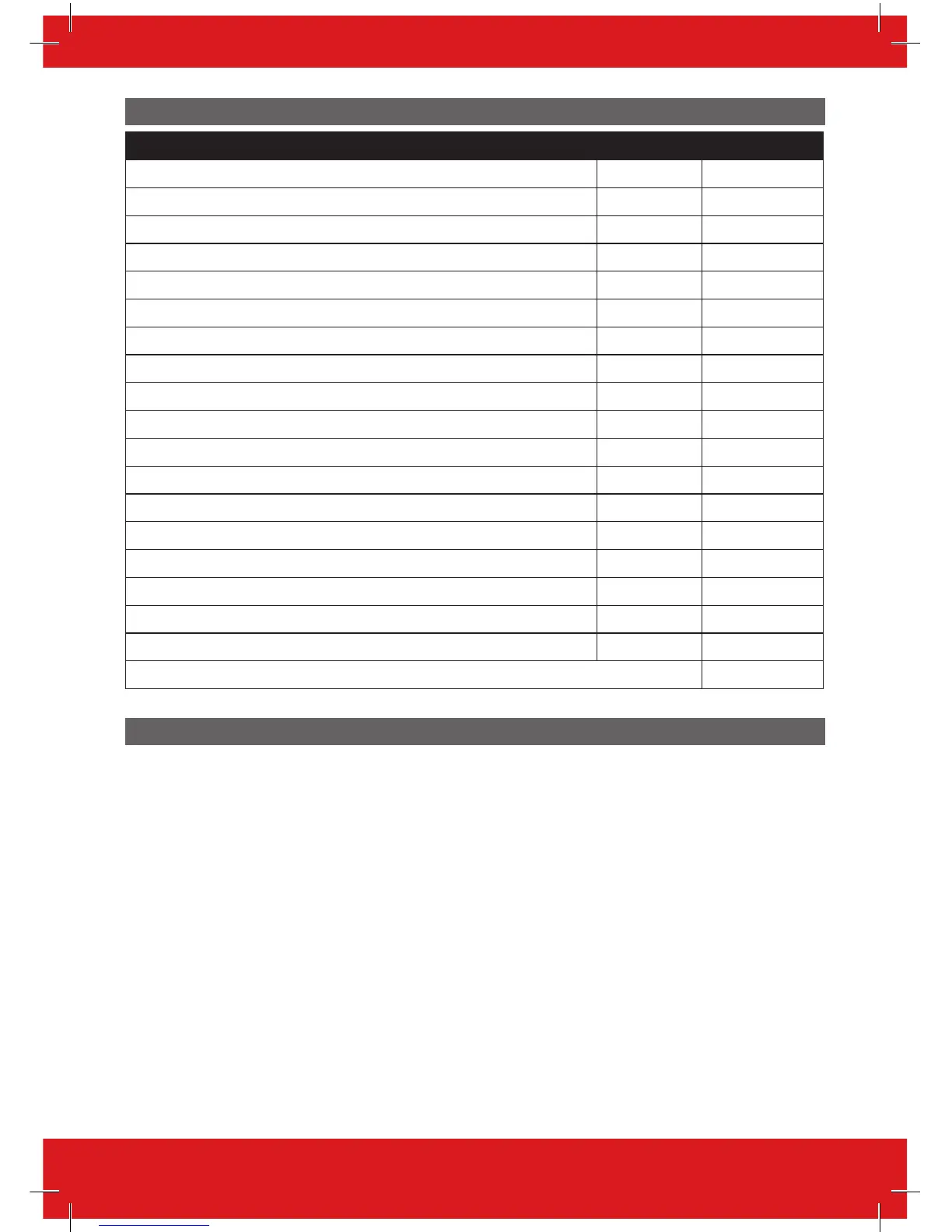
Output Mapping
Devices Address Outputs Numbers
EURO 46 V10 APP PCB N/A 5 (2 shared)
Digi/ATE Outputs (using communication loom) N/A 10
EURO-OEM8R8T / EURO-OEM16R+PSU 0 1-16
EURO-OEM8R8T / EURO-OEM16R+PSU 1 17-32
EURO-ZEM8+/ EURO-ZEM8+PSU 0 1-4
EURO-ZEM8+/ EURO-ZEM8+PSU 1 1-4
EURO-ZEM8+/ EURO-ZEM8+PSU 2 1-4
EURO-ZEM8+/ EURO-ZEM8+PSU 3 1-4
EURO-ZEM8+/ EURO-ZEM8+PSU 4 1-4
EURO-ZEM8+/ EURO-ZEM8+PSU 5 1-4
EURO-ZEM8+/ EURO-ZEM8+PSU 6 1-4
EURO-ZEM8+/ EURO-ZEM8+PSU 7 1-4
EURO-LCD/EX 0 1
EURO-LCD/EX / EURO-PROX/INT / EURO-EXT-BK/W 1 1
EURO-LCD/EX / EURO-PROX/INT / EURO-EXT-BK/W 2 1
EURO-LCD/EX / EURO-PROX/INT / EURO-EXT-BK/W 3 1
EURO-LCD/EX / EURO-PROX/INT / EURO-EXT-BK/W 4 1
EURO-LCD/EX / EURO-PROX/INT / EURO-EXT-BK/W 5 1
Total 85
Regulatory Wiring Requirements
• Ensure wiring is done to the national wiring regulations in the country where the installation is
taking place. In the UK, this is BS 7671 Requirements for electrical installations; IET Wiring
Regulations (17th edition). If in doubt, consult a local qualified electrician.
• Ensure that a readily accessible disconnect device incorporated in the premises installation wiring
shall be provided external to the equipment with a contact separation of at least 3,0mm and
connected as closely as possible to the supply. Example: Fused Spur Unit
• When fixing external wires, ensure that means are provided in the installation to prevent the SELV
(Safety Electrical Low Voltage) or signal circuits from coming into contact with live parts of the
power supply circuit. Wires shall be fixed near their terminal blocks.
• The end of stranded conductor shall not be consolidated by soft soldering at places where the
conductor is subjected to contact pressure. Example: Must not solder ends of wires which are to be
secured in detector and control panel terminal connectors.
• On completion of wiring use tie-wraps to prevent any loose wires causing a safety hazard (material
of cables tie shall be rated at least HB or better).
• Cables ties and sleeves shall be separate for power supply cable and SELV (Safety Electrical Low
Voltage) wirings.
• Size of protective bonding conductors: minimum section 1.5mm². Example: Electrical Earth wire
connections.
 Loading...