28
ELECTRICAL RETRACTORS INSTALLATION
o
Electrical Retractors are designed and tested to ONLY be used in the front positions together with Q’Straint® 4-Point
Securement Systems.
o
Mounted Electrical Retractors MUST be clear of any obstructions and in an area where they can not be damaged due to
moving passengers or any transported goods within the vehicle.
o
Electrical Retractors MUST be mounted in a horizontal plane to ensure that the webbing does not jam or at a 30 degree
angle using Q’Straint® Bracket (part # Q8-6510).
o
When the Electrical Retractors are tted into the vehicle’s electrical system, they must be suitably fused, switched,
grounded and a compatible wire gage MUST be used. As well as the proper protection of the wires from dirt and
moisture.
o
When the Electrical Retractors are correctly tted and wired, they will restrain a maximum of 15kN (3,300lbs) frontal
rebound force and can be locked and unlocked as follows:
• Power On = retractors are released, webbing moves in and out of retractor.
• Power O = retractors are locked, webbing will not come out, but it will self-retract.
INSTALLATION CHECKLIST
ELECTRICAL REQUIREMENTS
• The Electrical Retractors MUST be connected to the vehicle’s electrical system.
• 12VDC 1.5 amps
• Compatible with all 12 Volt vehicles.
ELECTRICAL RETRACTOR FAILSAFE SYSTEM REQUIREMENTS
• Vehicle must come to a complete stop and parking brake applied, then connect 12VDC power to Electric Retractors.
• All systems require a 12 VDC connected to the Electric Retractors and isolated through an Electrical Switch.
• The two wire connectors need to be placed near the Electrical Retractors and properly secured, covered and protected from the elements.
• Voltage to the Electric Retractors can only be initiated through the activation of the Electrical Switch.
• All systems require a second switch that de-energizes the relay by removing voltage from the Electrical Retractors.
• In addition to these manual controls, the Electric Retractor installation MUST be equipped with fail-safes that help prevent Electric
Retractors from being released while the vehicle is moving.
• One or more of the following examples are recommended, and must be used:
1. An electric timer that cuts the voltage to the Electrical Retractors within a 2 minute window of their activation.
2. A tailgate, door or ramp switch that removes voltage to the Electrical Retractors when the tailgate or ramp door is closed
and the ramp is stowed.
3. A parking brake switch that removes voltage to Electrical Retractors when the parking brake is released.
4. A transmission switch that removes voltage to Electrical Retractors when transmission is out of park.
5. A warning light that illuminates when the 12 volts is applied to the Electrical Retractors—
this is not a fail-safe, only a visual warning.
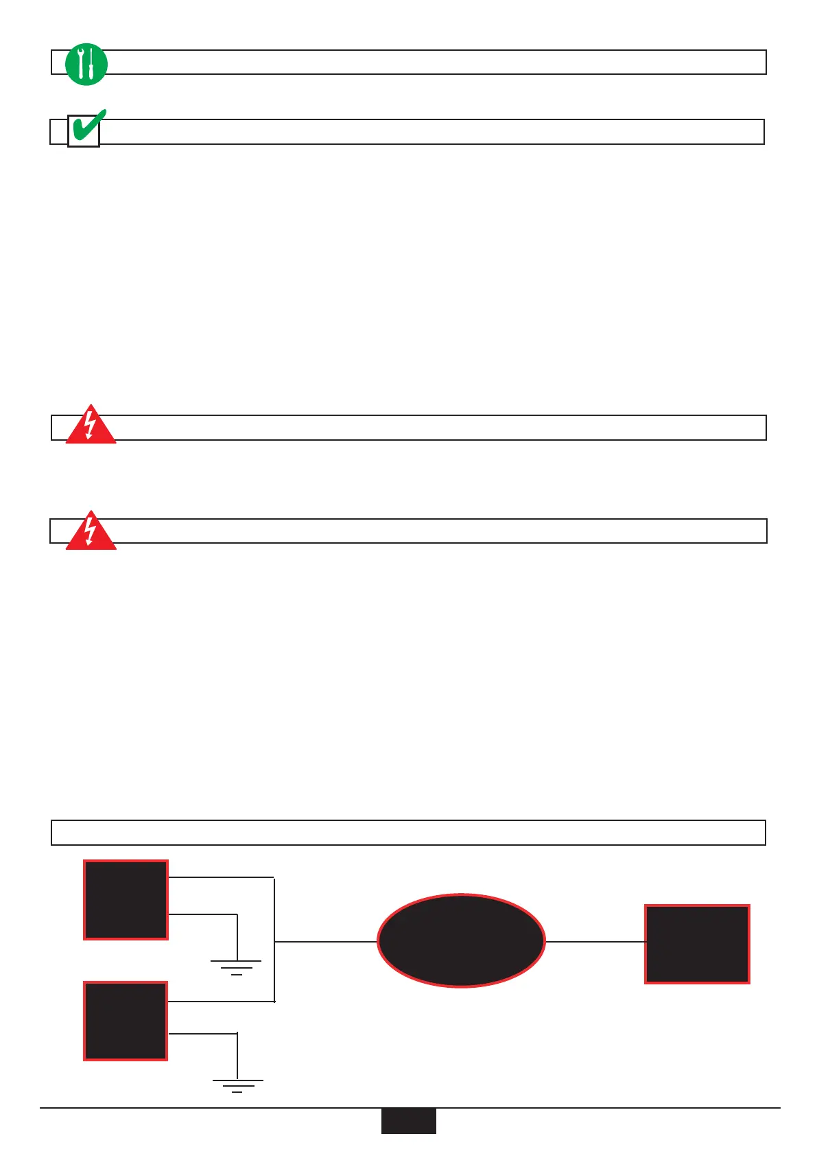
Retractor 2
VBATT
12Vdc
Required
Fail-Safe
Controls
RED
BLK
RED
BLK
Retractor 1
ELECTRICAL LAYOUT

 Loading...

