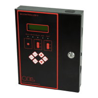
M-Controller II System Operation Manual - 7 -
84350-201-001 Rev C
It’s not used for Alarm-Sounding Appliance.
For external Alarm-Sounding Appliance, they can be connected to
the below Horn/Strobe terminal blocks, the Alarm-Sounding
Appliance sound-pressure level should be at least 85dB at 10 feet
according standard UL2017 Audibility Test
Horn & Strobe
Two relay dry contact are for Horn and Strobe
Dedicated 24VDC terminals are supplied for connection to
standard strobe and horn set.
Strobe relay can be set to 50% duty of pulse or 100% duty ON
Maximum of 750mA on the 24VDC power supply
Remote Devices
4x RS-485 Ports with QEL Controller Protocol
- Available QEL digital transmitters, such as Q5C
- Available I/O box: M-Relay, M-Annunciator, QRP
Modbus Slave
Port
Or
BACnet Port
RS-485 port, default setting is for Modbus protocol
_ Responds as a Modbus Slave using RTU protocol.
M-Controller supplies read status information only
_ Connect to QEL BACnet/IP module BAC-Box
The BACnet must be enabled in the BACnet MENU
Analog Output
Optional added circuit card to support 8 channels of 4-20
milliamps. The output signals and ground are isolated from the
M-Controller.
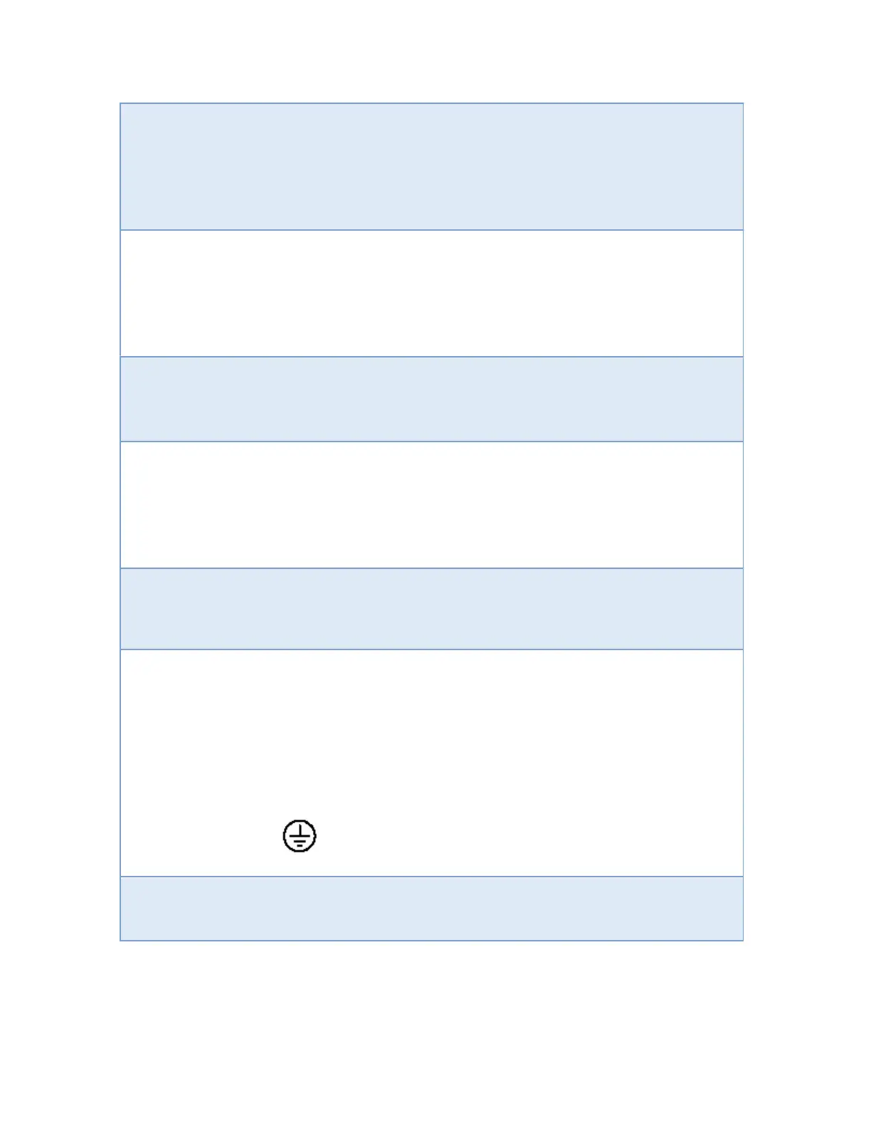
Grounding
A protective conductor (earth wire) must be connected from the
M-Controller grounding terminal to the electrical earth of the
installation. A grounding point is provided inside the unit in the
top right corner of the base of the enclosure.
The protective conductor terminal is marked with the following
symbol:
Certification
Standard UL 2017 2
Edition 2008