page 14
Appendix D
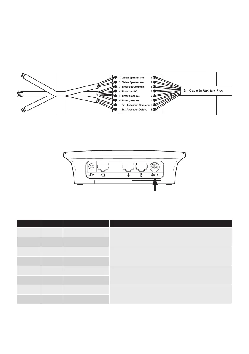
Pro9 auxiliary connections (Q-P9ACB)
If your system is using a lane timer and/or a chime speaker use an Auxiliary Connection Box and follow
these connection instructions:
Plug this interface connection unit into the corresponding connector on top of the base station.
This table provides the information you may require in relation to the auxiliary connections.
Connection Colour Description Notes
1 white Chime speaker +ve
For connection directly to a speaker to provide a chime on arrival of
a vehicle at the order point.
2 red Chime speaker -ve
3 blue Timer out common
0v switch output to provide vehicle detection to OEM timers or
other equipment.
4 green Timer out NO
5 brown Timer greet +ve
Simulated voltage output triggered when headset goes live to
speaker post. Provides “greet” function to OEM timers.
6 grey Timer greet -ve
7 purple Ext activation common
0v to 12v detection to provide third party activation of the
headset system. Typically output from an OEM timer system.
8 yellow Ext activation detect
Figure 19 - base station (top)
Figure 18 - Auxillary connector box connections
Chime
Ext activation
Timer