Appendix C
Installing Pro9 system using existing cabling to connect the base station to the DTM located in
the building (Q-P9JB x2)
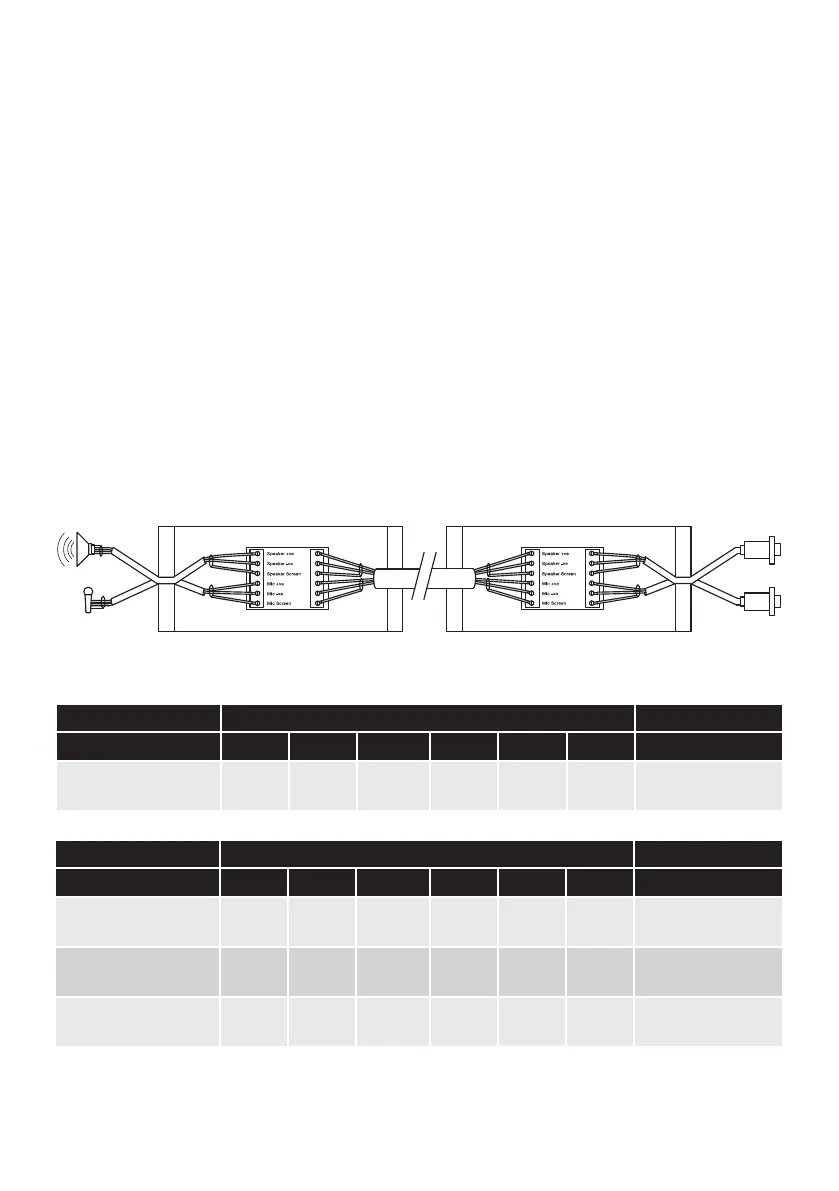
Using the junction boxes allows existing cabling to be used to carry the audio signals for the speaker
and microphone. Inside each is a small PCB with two sets of screw terminals, A and B as shown. Follow
the steps below to make the correct connections.
1. Ensure the Quail Digital speaker and microphones are installed at the order point.
2. The installed speaker and microphone are equipped with fixed length cables, factory terminated
with DIN connections. The DIN terminated ends of these cables need to be reused indoors to
complete the speaker and microphone DTM connections.
3. Cut the cables on both the speaker and the microphone, ensuring there is at least 300mm length
on the connector end cables which are used to connect the internal Q-P9JB to the DTM speaker and
microphone sockets.
4. Strip the cable of all 4 ends and prepare the cores for connection.
page 13
A B
AB
Terminal connection Connector A
Installed cable type Spk +ve Spk -ve
Spk screen
Mic +ve Mic -ve
Mic screen
Notes
Quail speaker & mic red black screen white blue screen
Supplied installation
options
Terminal connection Connector B
Installed cable type Spk +ve Spk -ve
Spk screen
Mic +ve Mic -ve
Mic screen
Notes
Belden 8723 2 Pair red black nc white green
screen
(drain)
As used in many DT
installations
Belden 8777 3 Pair
red
(pr1)
black
(pr1)
screen
(pr2)
white
(pr2)
black
(pr2)
screen
(pr2)
General purpose cable
suitable for DT
3M Cable red black nc white blue screen
Specialised cable
designed for DT
Note – only screened cable can be used for audio connections.
Figure 17 - Connecting using existing cabling to DTM in building