page 11
Appendix B
Installing Pro9 system using existing cabling to connect the base station to the DTM located in
the order point (Q-P9NTEXT and Q-P9NTINT)
Using the network termination boxes allows existing cabling to carry
digital signals and power on previously installed cabling. Inside each is a
small PCB with a network adaptor socket and screw terminals, as below.
Follow the steps on page 12 to make the correct connections.
1. Outdoors, strip back your existing cable and connect into the screw
terminals of the external network termination box (Q-P9NTEXT). Follow
the colour codes in the table below.
2. Indoors, strip back the other end of your existing cables and connect
into the internal network termination box (Q-P9NTINT). Follow the colour
codes in the table below.
3. At the order point connect the black Cat5 lead from the Q-P9NTEXT
into the DTM.
4. Indoors, connect the white Cat5 lead from the Q-P9NTINT to the base station.
5. In the order point connect the microphone and speaker into the connection strip of the junction
box as shown following the colour codes.
6. Connect your existing audio cable to section A of the PCB as shown below.
7. Then go to the other end of the audio cable in the building and use the other junction box to
attach the speaker and microphone plugs to it.
1 2 3 4 5 6 7 8
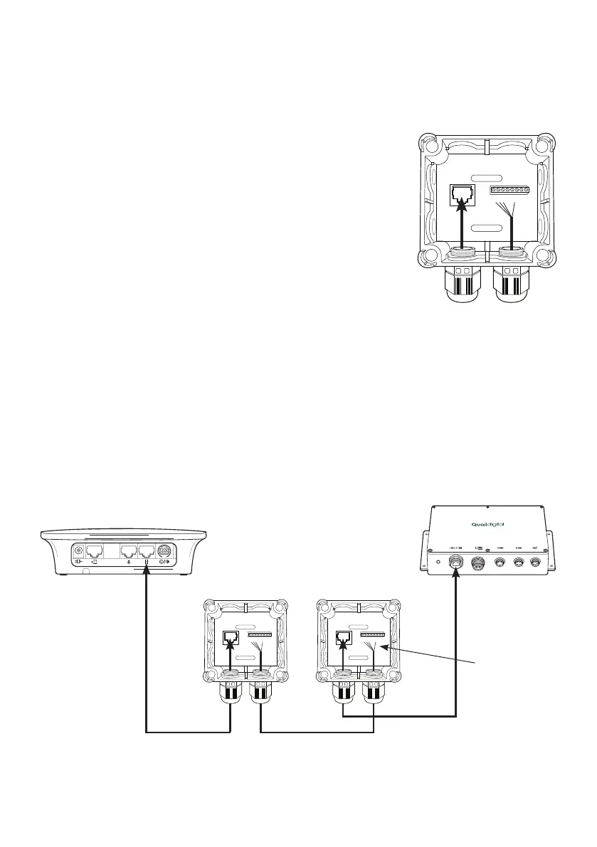
Figure 15 - Network
termination box
Base station
Figure 16 - Connecting using existing cabling to DTM in speaker post
PRO 9 DRIVE THRU MODULE
Q-P9DTM
DTM
Q-P9NTINT Q-P9NTEXT
White RJ45 ISP3 Belden
Black RJ45
1 2 3 4 5 6 7 8 1 2 3 4 5 6 7 8
1 red
2 black
3 white
6 black