ABOUT THE SYSTEM LED STATUS DEFINITIONS
1-11
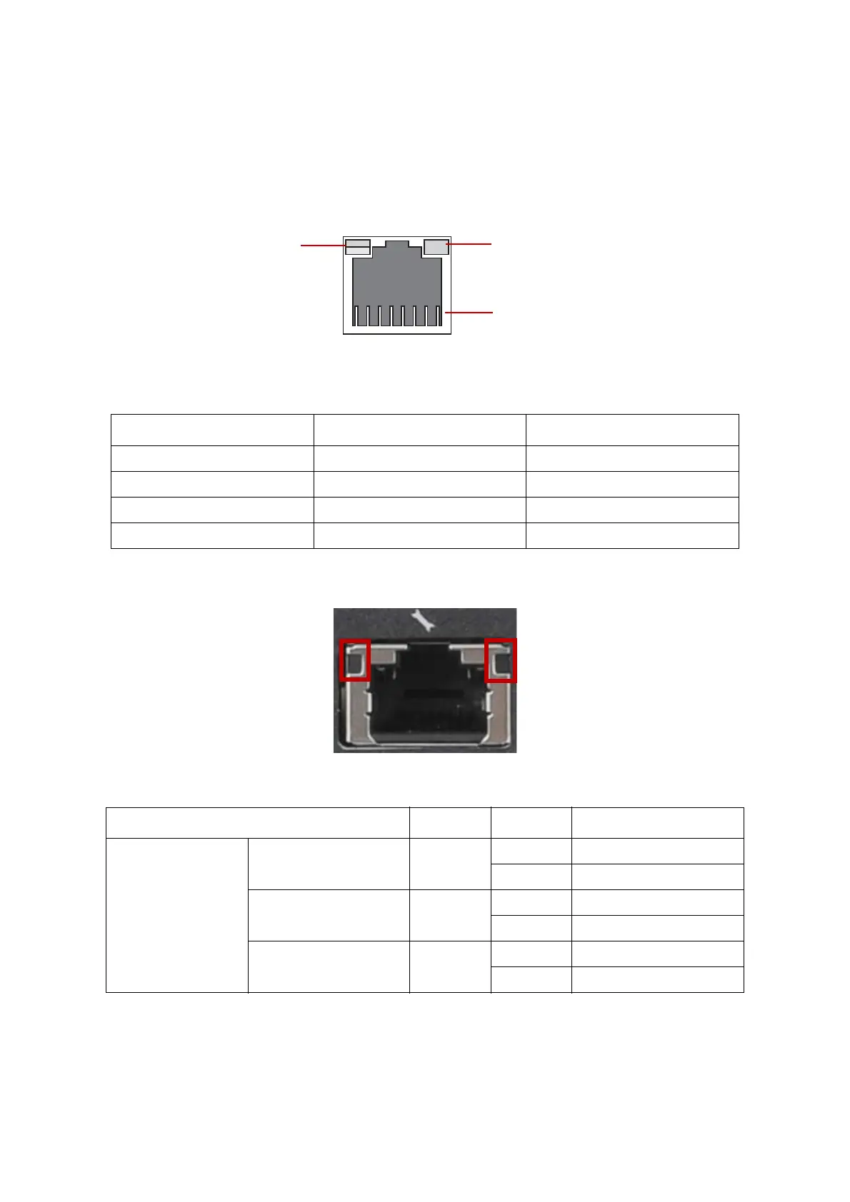
LAN LED
The system mainboard includes an optional dual 1GbE network with 1GbE dedicated
management port with an optional 10G SPF+ OCP network mezzanine card. Each RJ45
connector has two built-in LEDs. See the following illustration and table for details.
Figure 1-11. RJ45 LAN Connector
BMC Management Port LED
Table 9: RJ45 LED Description
CONDITION SPEED LINK / ACTIVITY
Unplugged Off Off
1G active link On amber Blinking green
100M active link On green Blinking green
10M active link Off Blinking green
Table 10: BMC Management Port LED Behaviour
NAME COLOR CONDITION BEHAVIOUR
BMC Dedicated LAN
Speed 1G (Left LED) Amber
ON LAN link
OFF No link
Speed 100M (Left LED) Green
ON LAN link
OFF No link
Activity (Right LED) Green
Blinking LAN Access
OFF No LAN Access
Speed
Link / Activity
PIN 1
Location