Chapter 2 Assembly & Installation
14
Models QT-740 & QT-750 - Service Manual
10. Position the collimator at 40" SID.
11. Pull the cassette film tray handle out so it extends out of the front opening in
table.
12. Turn on the collimator light.
13. Check for proper alignment of the image receptor centering light (emitted by
the collimator) with the notch in the cassette film tray handle. If misaligned,
refer to the collimator manual for alignment procedures.
TABLETOP ASSEMBLY/INSTALLATION
CAUTION! Be careful not to damage the Obstruc-
tion Sensors when installing the Tabletop Assem-
bly.
The following procedure describes how to install the Tabletop Assembly in the
Tab let o p Fram e.
1. Unpack the Tabletop Assembly from the carton.
2. At one end of the Tabletop Assembly, remove three (3) 1/4-20 x 1" low profile
socket head screws securing End Trim Plate to Tabletop Assembly.
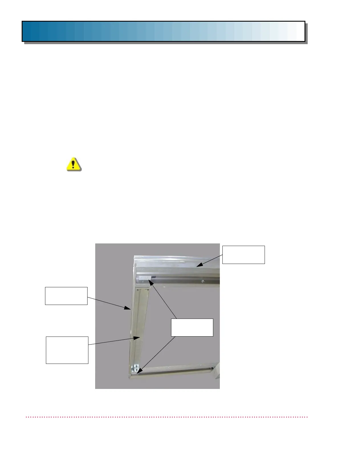
3. Remove two (2) Table Top End Stop Bumpers from Tabletop Frame (see Fig-
ure 6).
END STOP
BUMPERS
END TRIM
PLATE
Figure 6. Table Top End Trim Plate and End Stop Bumpers
TABLE TOP
ASSEMBLY
END
TABLETOP
SUPPORT
 Loading...
