Chapter 4 Service Instructions
44
Models QT-740 & QT-750 - Service Manual
Receptor Cabinet Removal/Replacement
The following procedure is performed with the radiographic portion of the
tabletop removed. To remove the radiographic portion of the tabletop, lift
up at one corner and pull off tabletop.
WARNING! To prevent electrical shock hazards,
make sure power is off before proceeding.
1. On systems equipped with a moving grid (bucky), tag and discon-
nect wires connected to bucky terminal strip.
2. Remove eight (8) 10-32 x 1/2" screws securing Receptor Cabinet
to Receptor Cabinet Mounting Bracket and remove cabinet.
3. Place new Receptor Cabinet inside Receptor Cabinet Mounting
Brackets and install eight (8) 10-32 x 1/2" screws. Do not tighten
screws.
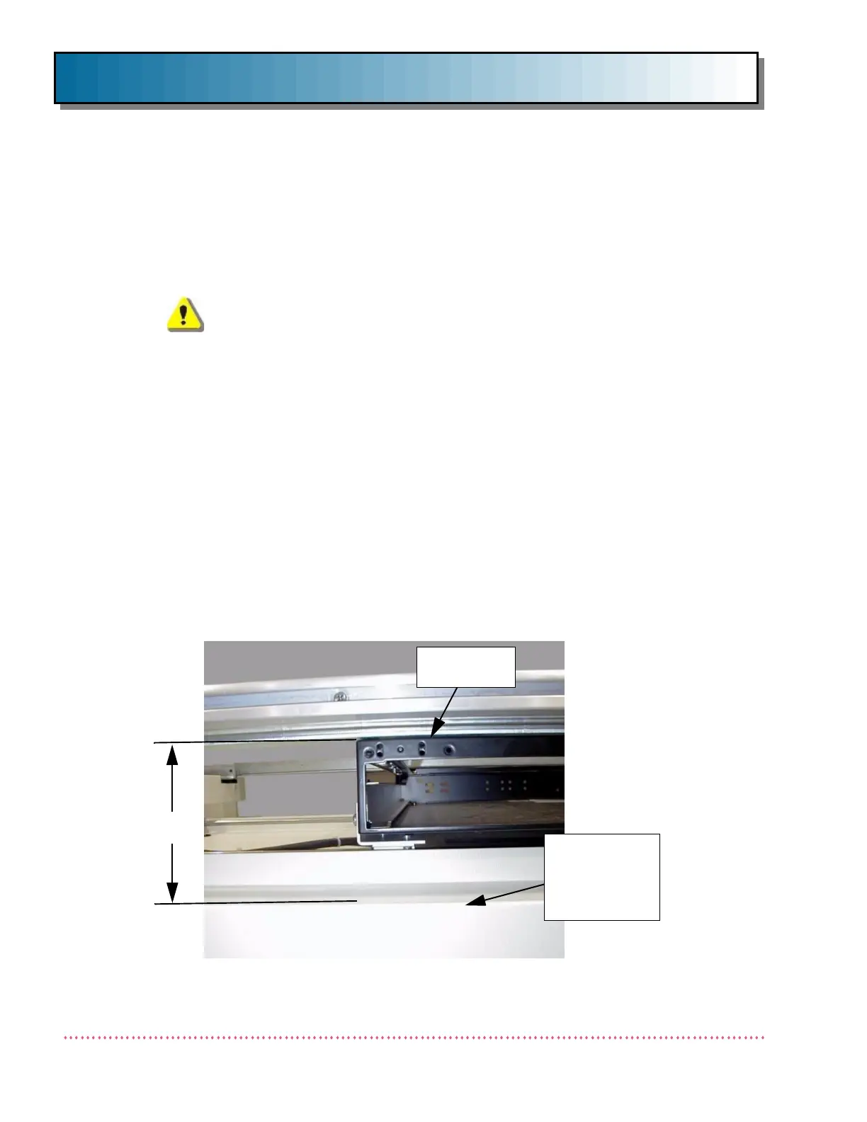
4. Position Receptor Cabinet in brackets so that the distance mea-
sured from the top of the Table Frame to the top of the receptor
cabinet is 4.25" (see Figure 21) at all four corners. When this
position is achieved, tighten Receptor Cabinet mounting screws.
5. Install radiographic portion of the tabletop. Slide the Receptor
Cabinet from one end of the table to the other and ensure that
the movement is smooth. If not, re-check measurements as
described in the previous step.
4.25"
RECEPTOR
CABINET
Figure 21. Correct Distance for Receptor Cabinet Installation
TABLE TOP
FRAME (UPPER
FRONT COVER
RESTS ON
FRAME)
 Loading...
