Chapter 4 Service Instructions
Models QT-740 & QT-750 - Service Manual
43
4. Disconnect plug from connector on DC Motor Driver Board A2.
5. Remove four (4) screws securing DC Motor Driver Board A2 to
Board Mounting Bracket and remove board. Retain screws for re-
assembly.
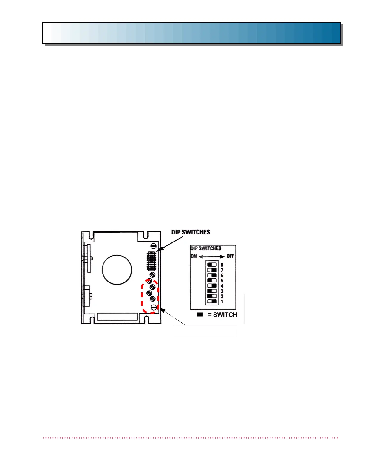
6. On replacement DC Motor Driver Board A2, verify that all five
potentiometers are turned fully clockwise (see Figure 20).
7. Set DIP switches 1-8 on DC Motor Driver Board A2 as follows:
1 = OFF
2 = ON
3 = ON
4 = OFF
5 = ON
6 = OFF
7 = OFF
8 = ON
8. Position replacement DC Motor Driver Board A2 on Board Mount-
ing Bracket and secure using screws removed in previous step.
9. Connect plug into connector on DC Motor Driver Board A2.
10. Remove Safety Bracket.
11. Reinstall upper and lower table covers (refer to Chapter 2,
Assembly and Installation).
12. Turn on power. Perform an operational test and check table travel
and positions.
13. If necessary, readjust MOTOR SPEED potentiometer R20 on 6-
Way Table Control Board A1. (It is recommended that the travel
time (fully raised to fully lowered) remain in the range of between
10-17 seconds.)
Figure 20. DC Motor Driver Board A2 Layout
POTENTIOMETERS
 Loading...
