GV200 User Manual
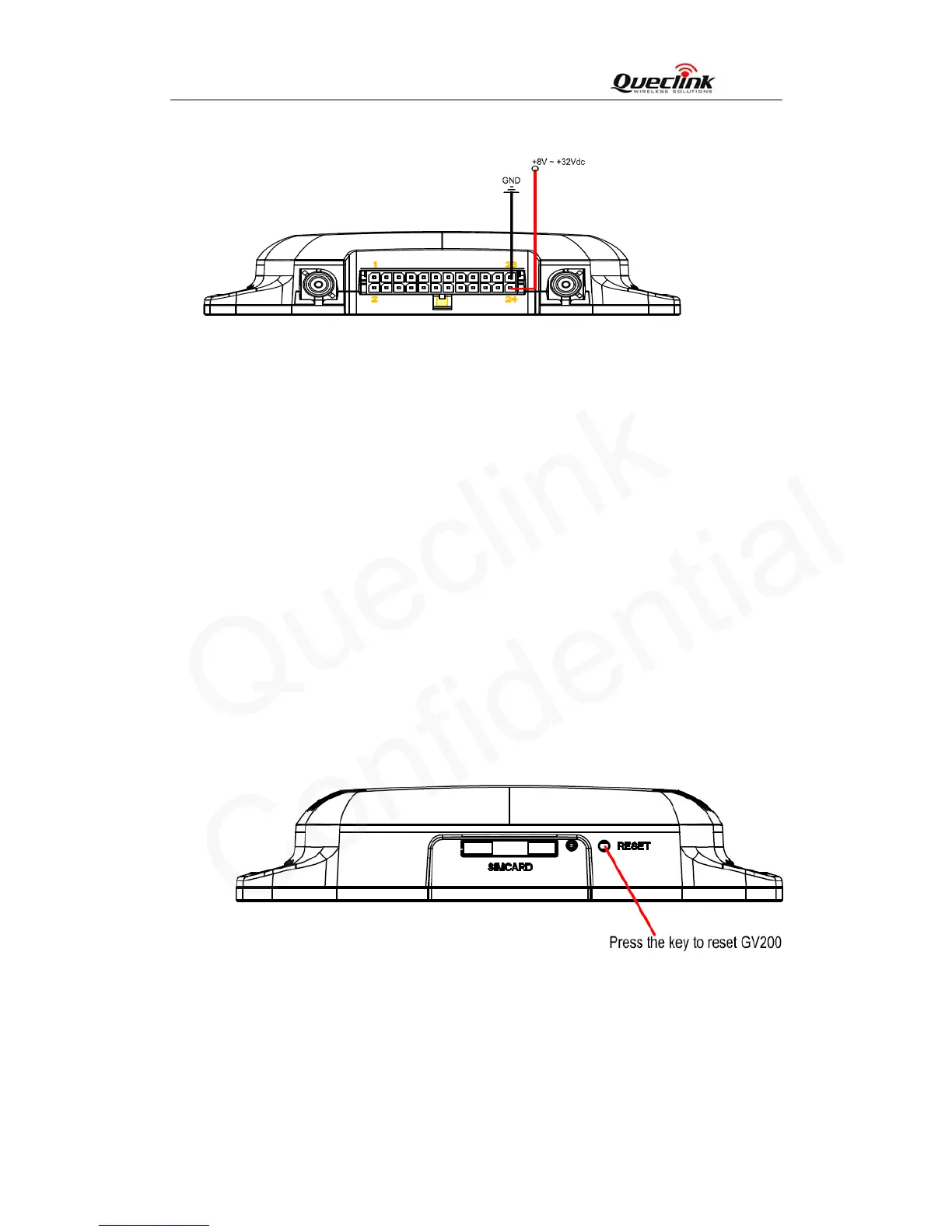
Please install the power like following.
Figure 6: Example of power connection
3.3.3. 5V Output
PIN 19 is named as VOUT which can drive a controlled 5V output for user. Please note that if
user wants to drive a 5V output, GV200 must be supplied by external power. In default, 5V
output is disabled, user can use AT commend to enabled 5V output. The max drive current of
VOUT is 0.25A.
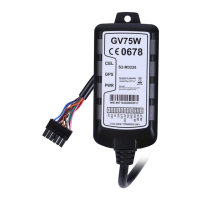
3.3.4. Reset Key
There is a reset key on the right side of SIM Card interface. When the key is pressed, the
device will reboot. Please note that reboot do not change any firmware parameter.
Figure 7: The key of reset
3.3.5. Ignition Detect
The PIN 14 is DIN1 (Positive trigger). Its electrical conditions are:
TRACGV200UM001 - 14 -