GV200 User Manual
Table 8: Electrical conditions of ignition detect
Logical State Electrical State
Active 5.0V to 32V
Inactive 0V to 3V or Open
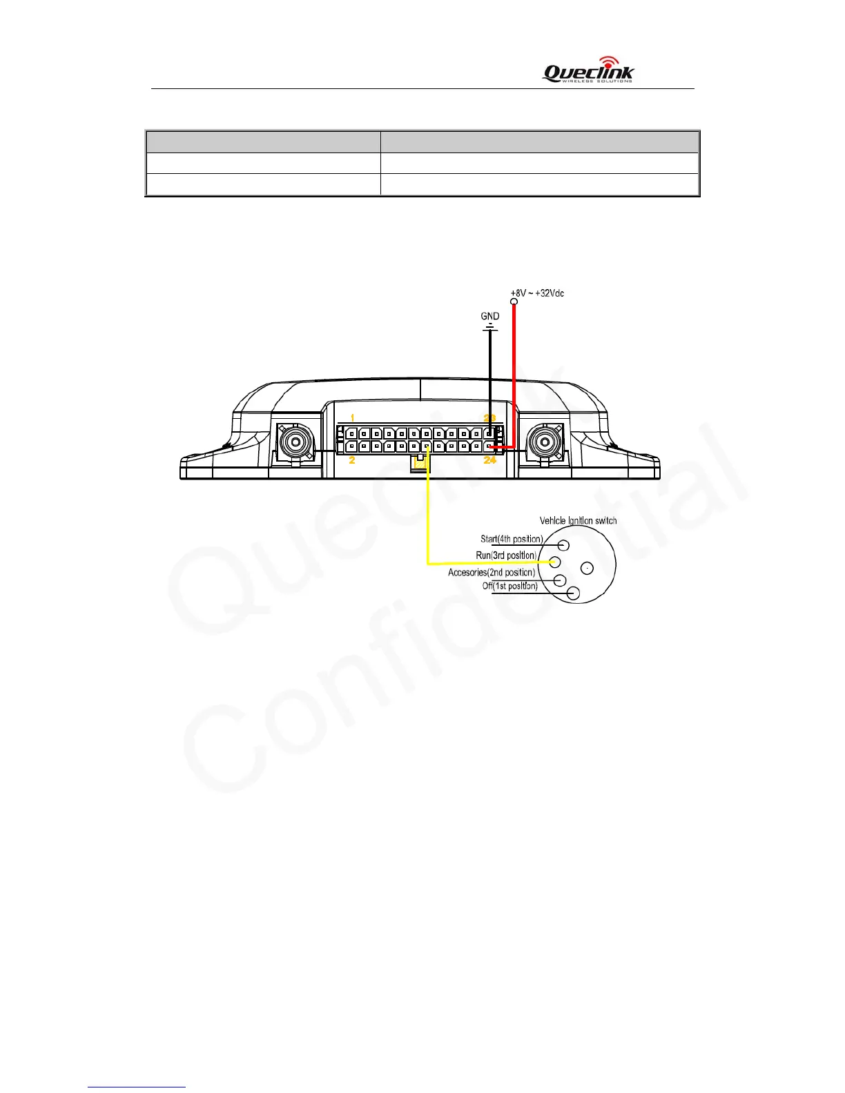
It is strongly recommended to connect this pin to ignition key to support the power saving
function when the vehicle is off.
Figure 8: Ignition detection
Another easy way is to connect PIN14 to a power output in the fuse box of the vehicle which
is only enabled after the vehicle is ignition on. For example: the power output for radio FM.
3.3.6. Ignition Control
DOUT1/2/3/4 can be used to control ignition key. They are Open-Drain type with no internal
pull-up resistor which also be used to control a relay. It means that the user has to connect a
pull-up resistor or a relay coil between the DOUT1/2/3/4 pin and any positive voltage (32V
max.) to generate a correct output. The DOUT1/2/3/4 pin can drive a continuous current of
0.2A.
The electrical conditions of it are:
TRACGV200UM001 - 15 -