LTE Module Series
EC25-V User Manual
EC25-V_User_Manual Confidential / Released 33 /
69
EC25 supports USIM card hot-plug via the USIM_PRESENCE pin. It supports low level and high level
detections, which is disabled by default. For details, refer to document [2] about the command
AT+QSIMDET.
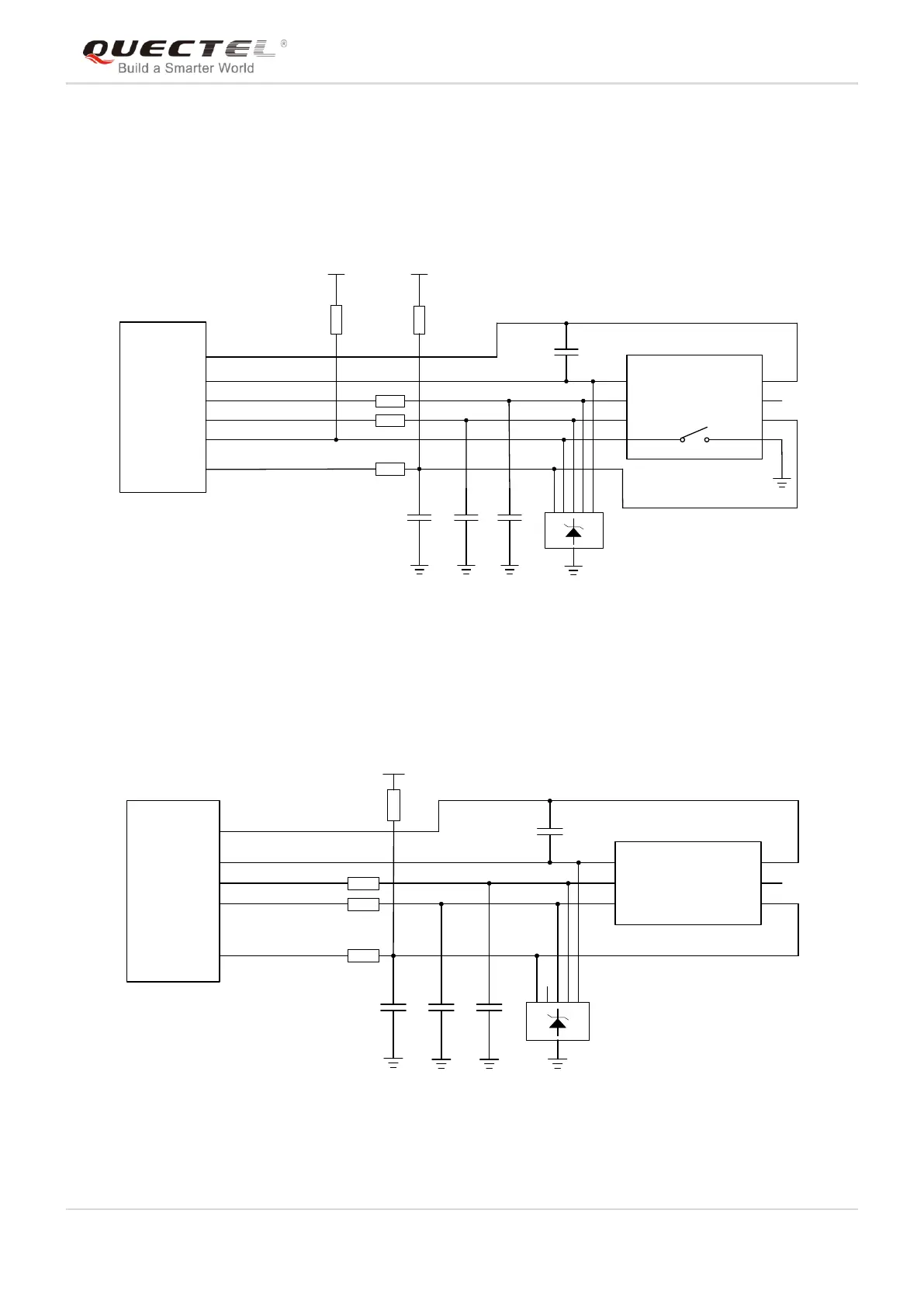
The following figure shows the reference design of the 8-pin USIM connector.
Module
USIM_VDD
USIM_GND
USIM_RST
USIM_CLK
USIM_DATA
USIM_PRESENCE
22R
22R
22R
VDD_EXT
51K
100nF USIM Connector
GND
GND
33pF 33pF 33pF
VCC
RST
CLK
IO
VPP
GND
GND
USIM_VDD
15K
Figure 17: Reference Circuit of 8-Pin USIM Connector
If you do not need the USIM card detection function, keep USIM_PRESENCE unconnected. The
reference circuit for using a 6-pin USIM card connector is illustrated in the following figure.
Module
USIM_VDD
USIM_GND
USIM_RST
USIM_CLK
USIM_DATA
22R
22R
22R
100nF
USIM Connector
GND
33pF 33pF 33pF
VCC
RST
CLK IO
VPP
GND
GND
15K
USIM_VDD
Figure 18: Reference Circuit of 6-Pin USIM Connector
In order to enhance the reliability and availability of the USIM card in your application, please follow the