Smart Module Series
SG560D_Series_Hardware_Design 109 / 134
5.4. Reference Design of RF Routing
When designing PCB, characteristic impedance of all RF traces should be controlled to 50 Ω. Generally,
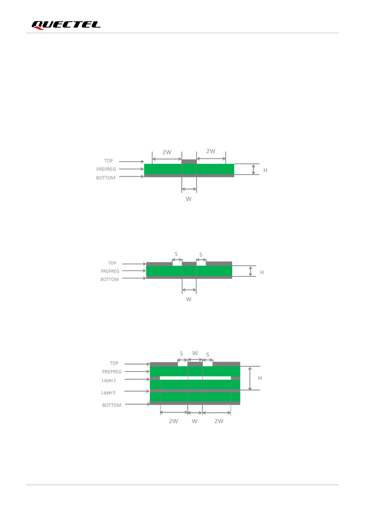
the impedance of RF traces is determined by materials’ dielectric constant, trace width (W), spacing
between RF traces and grounds (S) and height from the reference ground to the signal layer (H).
Microstrip or coplanar waveguide is typically used in RF layout to control characteristic impedance. The
following are reference designs of microstrip or coplanar waveguide with different PCB structures when
characteristic impedance of RF traces is controlled to 50 Ω.
Figure 31: Microstrip Design on a 2-layer PCB
Figure 32: Coplanar Waveguide Design on a 2-layer PCB
Figure 33: Coplanar Waveguide Design on a 4-layer PCB (Layer 3 as Reference Ground)








 To Next Page