Smart Module Series
SG560D_Series_Hardware_Design 62 / 134
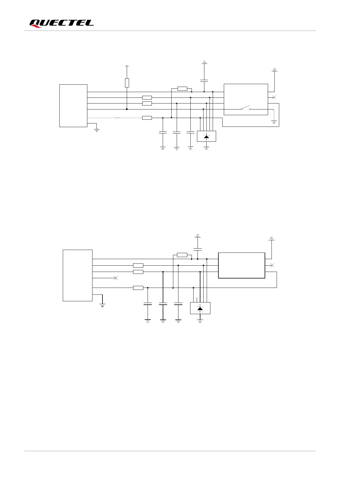
The following figure shows a reference design for (U)SIM interface with an 8-pin (U)SIM card connector.
Figure 15: Reference Circuit of (U)SIM Interface with 8-Pin (U)SIM Card Connector
If (U)SIM card detection function is not needed, please keep USIM_DET unconnected.
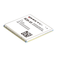
A reference circuit for (U)SIM card interface with a 6-pin (U)SIM card connector is illustrated in the
following figure.
Figure 16: Reference Circuit of (U)SIM Interface with 6-Pin (U)SIM Card Connector
To enhance the reliability and availability of the (U)SIM card in applications, please follow the criteria
below in (U)SIM circuit design.
⚫ Place the (U)SIM card connector as close to the module as possible. Keep the trace length as less
than 200 mm as possible.
⚫ Keep (U)SIM card signals away from RF and VBAT traces.
⚫ To avoid cross-talk between USIM_DATA and USIM_CLK, keep them away from each other and
shield them with surrounded ground. In addition, USIM_RST also needs to be shielded with
surrounded ground.




 To Next Page