Smart Module Series
SG560D_Series_Hardware_Design 76 / 134
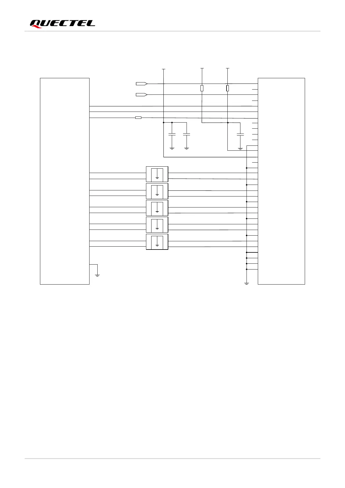
The following figure shows a reference design for LCM interface.
Figure 20: Reference Circuit for LCM Interface
MIPI are high speed signal traces. It is recommended to add common-mode filters in series near the LCM
connector to improve protection against electromagnetic radiation interference.
It is recommended to read the LCM ID register through MIPI when compatible design with other displays
is required. If several LCMs share the same IC, it is recommended that the LCM module factory should
burn an OTP register to distinguish different screens. You can also connect the LCD_ID pin of LCM to the
ADC pin of the module, but note that the output voltage of LCD_ID should not exceed the voltage range of
the ADC pin.
You can design external backlight driver circuit for LCM according to actual requirement. The reference
design is shown in the figure below, in which PWM1 is used for backlight brightness adjustment.




 To Next Page