Smart Module Series
Smart_EVB_G5_User_Guide 8 / 66
Figure Index
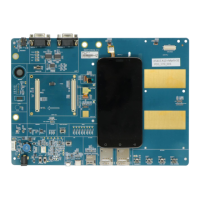
Figure 1: Smart EVB G5 Top View .................................................................................................................... 13
Figure 2: Smart EVB G5 Bottom View ............................................................................................................... 14
Figure 3: Top View for Component Placement of Smart EVB G5 ..................................................................... 15
Figure 4: Bottom View for Component Placement of Smart EVB G5 ............................................................... 16
Figure 5: Smart EVB G5 and Accessories......................................................................................................... 19
Figure 6: Smart EVB G5 Kit Accessories .......................................................................................................... 20
Figure 7: Simplified Power Supply Block Diagram of Smart EVB G5 ............................................................... 23
Figure 8: 5 V DC Power Jack ............................................................................................................................ 23
Figure 9: Power Plug Design ............................................................................................................................. 23
Figure 10: Reference Design for Battery Interface ............................................................................................ 24
Figure 11: Pin Assignment of Battery Interface ................................................................................................. 24
Figure 12: B2B Connectors ............................................................................................................................... 26
Figure 13: Sketch Map of Smart TE-A (Top View) ............................................................................................. 26
Figure 14: Reference Design for Main LCM Interface ....................................................................................... 35
Figure 15: Reference Design for Secondary LCM Interface ............................................................................. 36
Figure 16: Pin Assignments of LCM Interfaces ................................................................................................. 37
Figure 17: Reference Design for Backlight Driver ............................................................................................. 37
Figure 18: Reference Design for Touch Panel Interfaces .................................................................................. 38
Figure 19: Pin Assignments of Touch Panel Interfaces ..................................................................................... 38
Figure 20: Reference Design for Camera Interfaces ......................................................................................... 40
Figure 21: Camera Interfaces with Cameras Assembled .................................................................................. 41
Figure 22: Reference Design for USB Interfaces .............................................................................................. 42
Figure 23: USB Interfaces ................................................................................................................................. 42
Figure 24: Reference Design for Loudspeaker Interface .................................................................................. 43
Figure 25: Reference Design for Headset Interface .......................................................................................... 44
Figure 26: Pin Assignment of Headset Interface ............................................................................................... 44
Figure 27: Sketch of Audio Plug ........................................................................................................................ 45
Figure 28: Reference Design for Earphone Interface ........................................................................................ 46
Figure 29: Reference Design for Microphone Interfaces ................................................................................... 46
Figure 30: MEMS-Type and ECM-Type Microphones ....................................................................................... 47
Figure 31: Reference Circuit for (U)SIM Interface with (U)SIM1 Card Connector ............................................ 48
Figure 32: Pin Assignment of J1001 and J1002 ................................................................................................ 48
Figure 33: RS-232 Level Match Circuit.............................................................................................................. 50
Figure 34: Pin Assignments of Main UART and Debug UART .......................................................................... 50
Figure 35: Simplified Interface Schematic for SD Card Interface ...................................................................... 51
Figure 36: Pin Assignment of SD Card Interface ............................................................................................... 52
Figure 37: Reference Circuit Design for Flashlight Interfaces ........................................................................... 53
Figure 38: Flashlights ........................................................................................................................................ 53
Figure 39: Sensors ............................................................................................................................................ 54
Figure 40: Reference Design for USB_BOOT ................................................................................................... 55
Figure 41: Reference Design for Vibrator .......................................................................................................... 55