31
Quicksilver 810 Arvor — System & Component Overview and Operaon
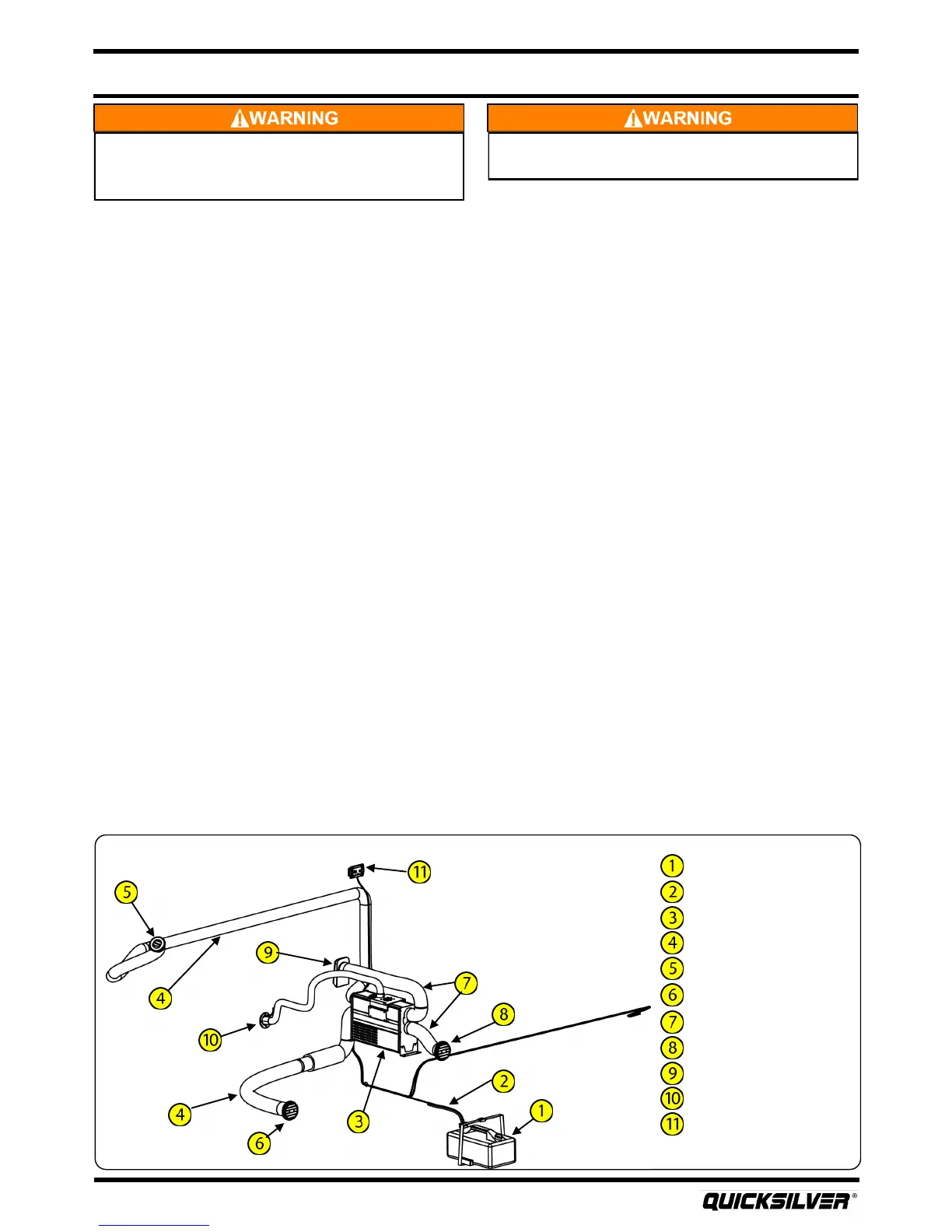
10L diesel tank
Fuel line
Diesel heater
Hot air ducts
Window defroster
Cabin vent
Cold air ducts
Cabin return air vent
Exterior return air vent
Exhaust outlet
Heater controller
Diesel Heat
Vision from the exterior helm staon is limited. Maintain a
lookout as required. Do not operate at planing speeds from
the exterior helm.
DO NOT TURN THE STEERING WHEEL AT THE HELM
THAT DOES NOT HAVE FULL CONTROL OF THE BOAT.
Maintenance
A hydraulic steering system rarely needs to be relled aer the system is bled. However, if you ever
need to add uid to the system, refer to the steering manufacturer’s manual for complete
instrucons.
REFER TO OWNER’S MANUAL PACKAGE FOR INSTRUCTIONS AND WARRANTY INFORMATION.
19. Diesel Heat (oponal)
The diesel heat system consists of a 3kW heater, a 10L diesel tank providing fuel for the heater, and a
control panel that runs the system.
Operaon
Prior to use, make sure that the diesel tank is full. The 10L diesel tank, located in the starboard bilge,
can be accessed via the forward cockpit oor hatch. To ll the tank, rst remove the strap holding
the tank in place. Next, remove the cap with the fuel pickup and pull the tank out of the boat.
ALWAYS FILL THE TANK OUTSIDE OF THE BOAT. When lled, re-install the cap, and secure the tank in
the bilge.
The diesel heater is controlled by a keypad located inside the cabin on the starboard pilaster. The
panel allows for either automac control of a preset temperature, or it allows you to vary the blower
speed and temperature manually. There are two heang ducts throughout the boat. First, there is a
closable outlet located at the dash to defrost the windows for visibility. Next, there is a direconal
outlet located below the helm seat providing heat to the cabin area.
The heater pulls air from two locaons; the rst cold air inlet is located below the cabin bench seat
and the second is an exterior inlet located on the starboard side of the deckhouse. Finally, there is an
exhaust outlet located on the starboard hullside where hot exhaust exits the unit.
REFER TO OWNER’S MANUAL PACKAGE FOR INSTRUCTIONS AND WARRANTY INFORMATION.