RD4000 Locating System User Manual
Page 18
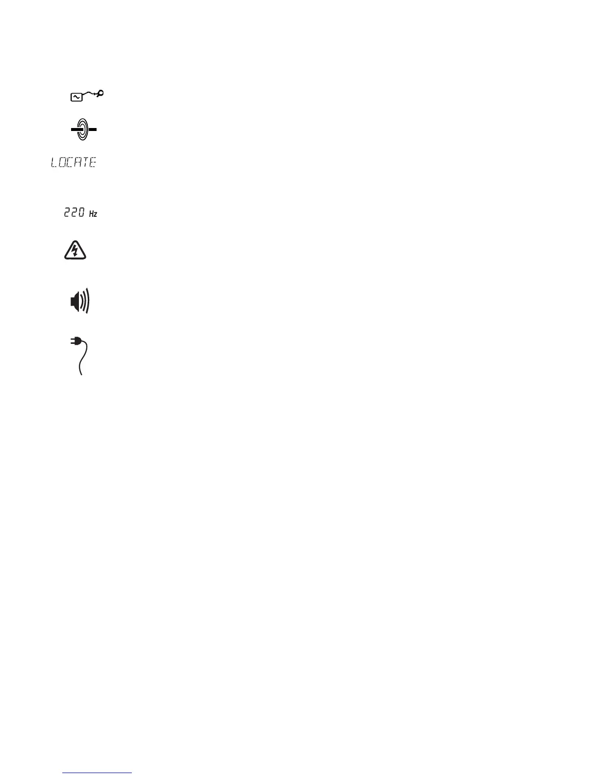
(13) Clamp connected indicator.
Symbol is displayed when a clamp is connected to the transmitter.
(14) Direct connection indication.
Shows that the transmitter is connected to the line by direct connection.
(15) Text display.
Displays operating mode, frequency submode, and menus/alarms. Also scrolls the text ‘HI
POWER’ from right to left when the transmitter is generating more than 5 watts.
(16) Numeric indicator.
Displays output frequency.
(17) HI VOLTS warning indicator.
Indicates that the transmitter is capable of outputting more than 30 volts. When switched on, the
transmitter has HI VOLTS set to OFF and the transmitter cannot output more than 30 volts. Use
the transmitter menu to select HI VOLTS ON.
(18) Volume level.
Indicates the volume that the sounder is set to (off, low, mid, and high).
(19) External power supply indicator.
Indicates that an external power supply is connected to the transmitter.