Connector Description
42
Jumper settings
Speaker (J9)
The speaker connector pins are for use with an external speaker. To use the onboard speaker,
close pins 3-4 with a jumper.
CMOS clear (JRTC1)
Instead of pins, the "jumper" in JRTC1 consists of contact pads to prevent the accidental clearing
of CMOS. To clear CMOS, power off the system and remove the AC power cord. Use a metal
object, such as a small screwdriver, to touch both contact pads at the same time and short the
connection.
PCI slots to system management bus speeds (JI
2
C1)
This jumper allows you to connect PCI/PCI-Express slots to the System Management Bus. The
default setting is open to disable the connection.
Rear I/O panel — Triple audio
jacks
JA33331-H11P-4F HD audio phone jack vertical 1X3 port,Pb-
Free (JA33331-H11P-4F)
Rear I/O panel — RJ45 Gigabit
Ethernet port
SKT-0262L CNT,RJ45/dual USB,P35-152-19W9,Pb-Free
Rear I/O panel —USB ports SKT-0135L CNT, I/o-conn, usb*4/16pin, DIP/M/2, black,
P-B/PBT
RearI/O panel —VGA/DVI
connector
SKT-0268L DSUB24P-VGA-COM with screw lock,Pb-
Free
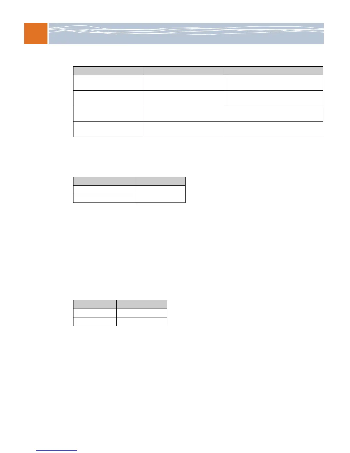
Table 25. Onboard connector part numbers
Onboard connector Part number Description
Setting Definition
Pins 3-4 jumpered Internal Speaker
Pins 1-4 External Speaker
Setting Definition
Jumpered Enabled
No jumper Disabled (default)
 Loading...