Connector Description
46
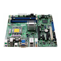
Clear CMOS jumper
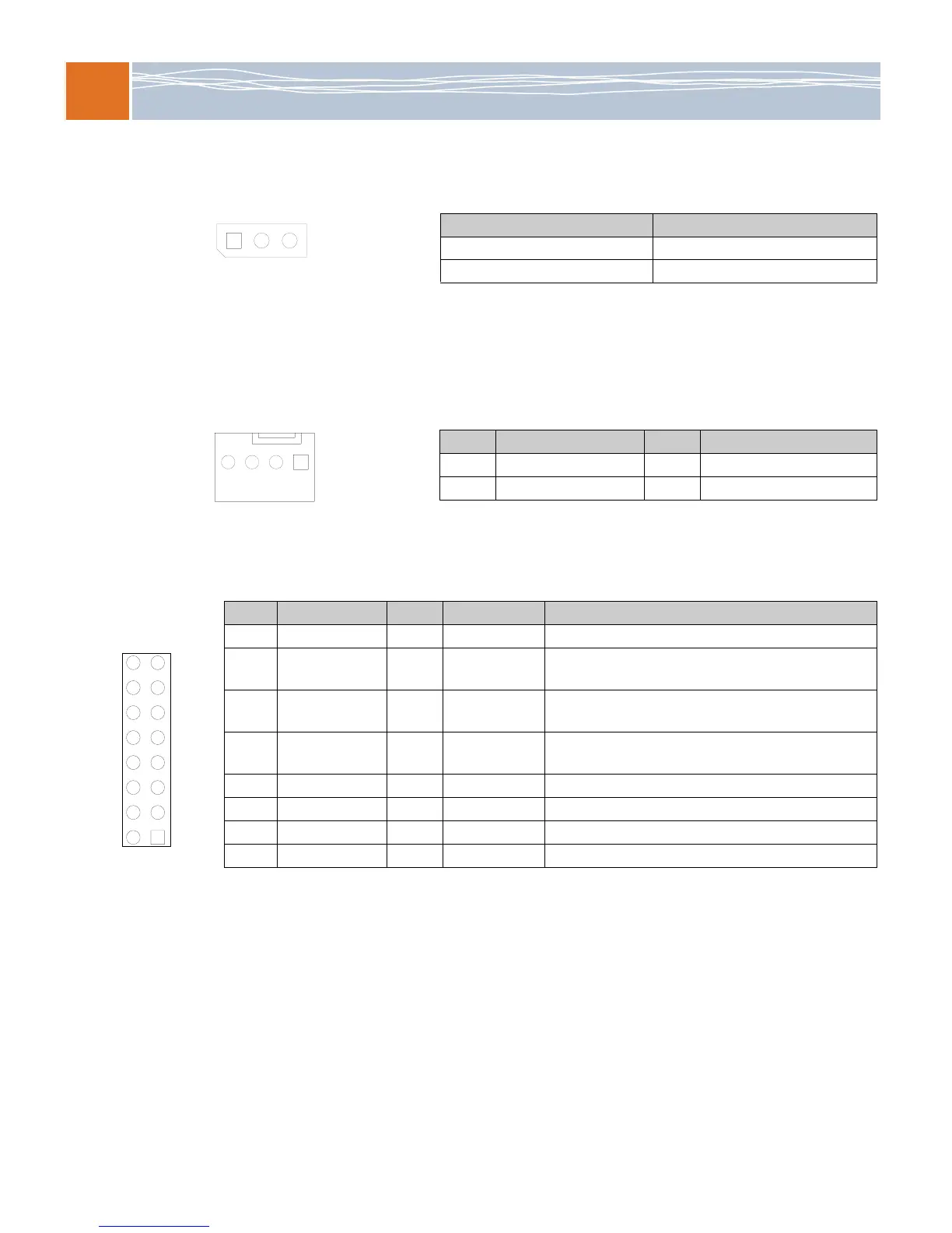
Fan header
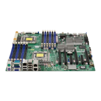
Front panel I/O header
Jumper setting Configuration
Pins 1 &2 jumpered (default) Normal operation
Pins 2 & 3 jumpered Clear CMOS
Pin # Signal Pin # Signal
1
GND
2
+12V
3
Tachometer
4
FAN_PWM
PIN# Description PIN# Description Wiring Notes
16 Power LED 15 LED_Anode+ Connect pins 15 and 16 to the power LED
14 HDD LED 13 LED_Anode+ Connect pins 13 and 14 to the hard disk drive (HDD)
LED to display disk activity
12 NIC1 LED 11 LED_Anode+ Connect pins 11and 12 to the NIC1 (network interface
controller) LED to display network activity
10 NIC2 LED 9 LED_Anode+ Connect pins 9 and 10 to the NIC2 LED to display
network activity
8 OH/Fan fail LED 7 LED_Anode+ Connect pins 7 and 8 to the overheat/fan failure LED
6 — 5 — Not connected
4 Ground 3 Reset button Connect pins 3 and 4 to the hardware reset button
2 Ground 1 Power button Connect pins 1 and 2 to the power button