RAM DBS II
Refrigeration Solid State Starter
________________________________________________________________
________________________________________________________________
________________________________________________________________
________________________________________________________________
________________________________________________________________
________________________________________________________________
________________________________________________________________
________________________________________________________________
________________________________________________________________
3.4 Derating Factor
WARNING! When a DBS enclosure is mounted in an environment not in
accordance with Paragraph 3.3 as described above, it must be
derated as follows:
• Derate starter size 1.5% per degree C above 40 degrees C Ambient Temperature or 0.75% per degrees
F above 104 degrees F Ambient Temperature.
• Derate starter size 1% for every 100m above 2000m or every 300 ft. above 6000 ft. elevation.
4.0 Wiring
• The DBS controller shall be wired in accordance with the National Electrical Code and any local codes that may
apply.
• Copper conductors for 75 deg. C (min.) shall be used for power and control wiring unless specified otherwise.
• Minimum recommended wire sizes are #14 AWG for control voltage and #12 AWG for line voltage.
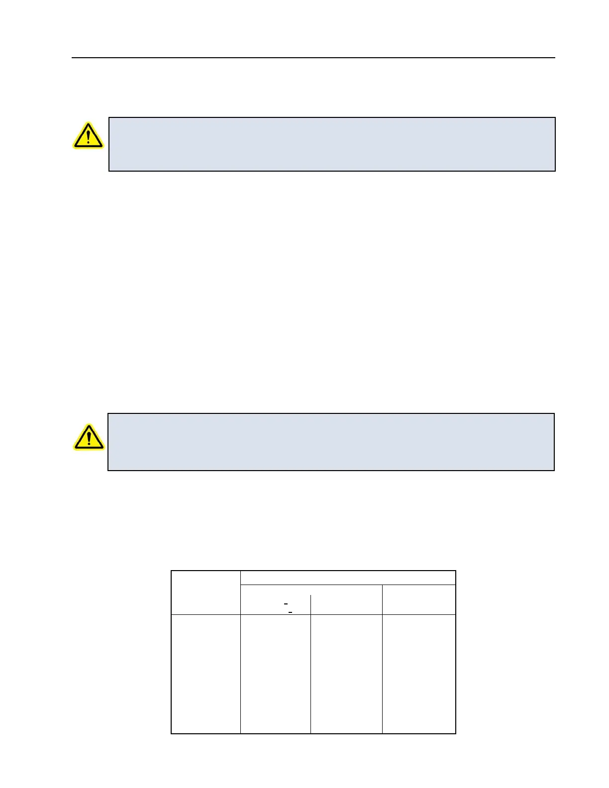
• Tighten connections per torque values shown on devices. Otherwise, refer to torque values in Table 8.
4.1 Incoming Power
Connect properly sized power wires to the input terminals on the DBS chassis marked L1, L2, & L3.
CAUTION! Incoming power wires must be connected in the correct order: L1, L2, L3.
Because the DBS controller is phase sensitive, it will not operate unless the
phase sequence is in this order. If not, a Phase Reversal trip will occur.
Avoid routing cable connections near the main circuit board. Refer to the National Electrical Code for
wire sizing and lug torque.
11
WIRE SIZE
(AWG or kcmil)
35
40
45
50
50
50
50
50
50
50
SLOTTED HEAD NO. 10 AND LARGER
20
25
35
35
40
Recommended Tightening Torque
UNLESS OTHERWISE NOTED ON INDIVIDUAL DEVICE
TABLE 8
18 -10
8
6 -4
3
2
1
1/0 - 2/0
3/0 - 4/0
250 - 400
500 - 750
HEX HEAD OR
SCREWS
SOCKET HEAD
SLOT WIDTH <3/64 IN
SLOT LENGTH <1/4 IN
SLOT WIDTH >3/64 IN
SLOT LENGTH >1/4 IN
TORQUE - IN/LB
75
75
110
150
150
150
180
250
325
375
4.0 Wiring