RAM DBS II
Refrigeration Solid State Starter
i
Appendix A
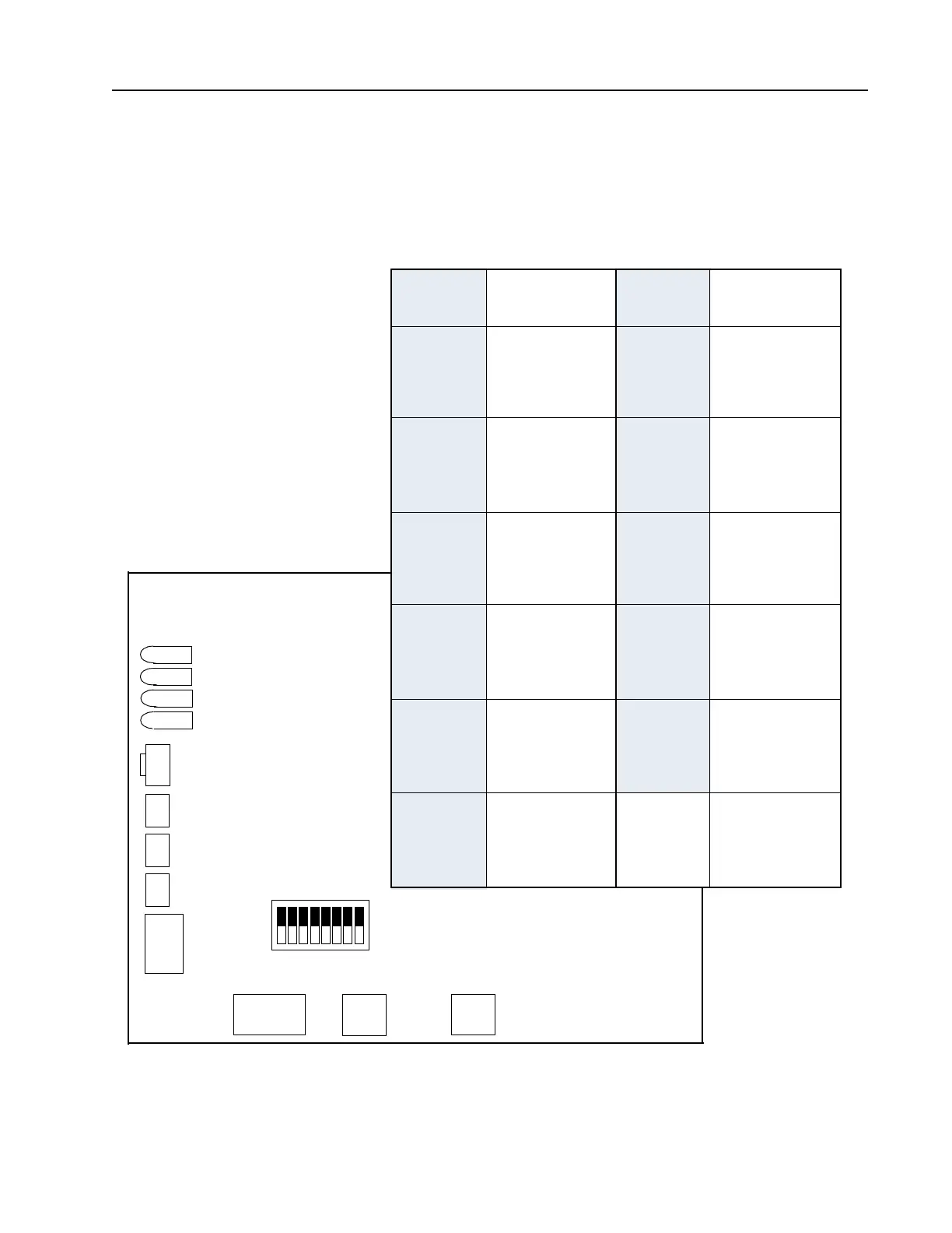
Starter Size Dipswitch Positions
to Determine Starter Size
FIGURE 9
Starter size DIP switch is located on the interior of the board (SW6). SW6 is positioned horizontally toward
the bottom of the board. Switch position #1 is farthest from the front edge of the board.
This switch is factory preset and should not be changed without factory approval.
STARTER
SIZE
STARTER
SIZE
1UP
2 DOWN
3 DOWN
4UP
1 DOWN
2UP
3 DOWN
4UP
1UP
2UP
3 DOWN
4UP
1 DOWN
2 DOWN
3UP
4UP
1 DOWN
2UP
3UP
4UP
B1
B2
B3
C1
C2
C3
SWITCH SWITCH
1 DOWN
2UP
3 DOWN
4 DOWN
1UP
2UP
3 DOWN
4 DOWN
1 DOWN
2 DOWN
3UP
4 DOWN
1 DOWN
2UP
3UP
4 DOWN
1UP
2UP
3UP
4 DOWN
1 DOWN
2 DOWN
3 DOWN
4UP
D1
D2
D3
E1
E3
SW6
STARTER SIZE
DIPSWITCH
87654
3
2
1
TB12
Network Port
1
2
3
tr+
tr-
gnd
Display Port
3
2
1
J2
Heatsink Sensor
gnd
signal
+5
J1
Configuration
SW4
SW3
SW2
SW1
Reset
SW5
LEDs
TRIP
ALARM
RUN
READY
UP = ON
DOWN = OFF
Appendix A
DOWN
UP
>
>