RAM DBS II
Refrigeration Solid State Starter
13
4.5 Field Connected Relay Outputs - TB1
The contacts of two relays on the DBS control board are available for controlling external devices
when not being utilized by the starter's basic control circuit. These contacts are connected to TB1
on the DBS control board. - See Figure 5, Section 4, for illustration of contacts and Table 3, Section
2, for contact values.
Run Relay - Energized when a start sequence is initiated.
N.O. Contact connected to terminals 7 and 8 may be used as a dry contact.
N.O. Contact connected to terminals 5 and 6 should be used ONLY as part of the start circuit.
Alarm Relay - Energized when an alarm condition exists.
N.O. Contact is connected to terminals 11 and 12.
N.C. Contact is connected to terminals 12 and 13.
4.6 Communication Ports - J1
Display Port - RJ-45 modular connector provides RS-232 communication for display. Refer to
Sections 8 and 9 for control/display unit operation. See Figure 5, Section 4.
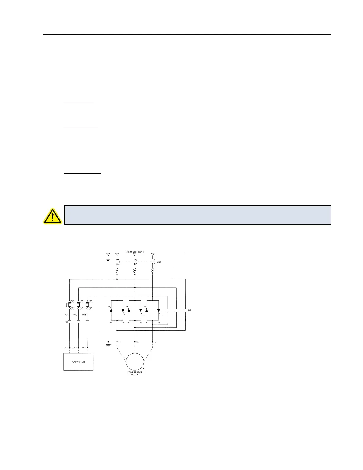
4.7 Power Factor Correction Capacitors (Option)
CAUTION! Power factor correction capacitors, when provided, shall always be connected
on the line side of the DBS controller.
4.8 Lightning Arrestor (Option)
A lightning arrestor is recommended in areas where frequent lightning occurs. It should be installed
on the line side of the controller’s circuit breaker.
FIGURE 4
4.0 Wiring