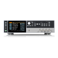
Instrument control
R&S
®
LCX Series
40Getting Started 1179.2254.02 ─ 03
4 = Signal parameters, see Chapter 6.2.1.5, "Signal parameters", on page 44
5 = Test signal monitor, see Chapter 6.2.1.6, "Test signal monitor", on page 44
6 = Measurement parameters and results, see Chapter 6.2.1.7, "Measurement parameters and
results", on page 44
The following sections explain the information areas as labeled.
6.2.1.1 Configuration preset indicator
The R&S LCX enables you to set up to three different measurement configura-
tions and assign them as favorites with the Chapter 6.2.1.4, "Configuration preset
softkeys", on page 43. The indicator displays the currently active preset configu-
ration.
(Preset 1/2/3) displays the currently active preset configuration.
6.2.1.2 Status bar
You can see two status bar lines. The status bar in the upper line on the right,
referred to as instrument status bar, indicates icons which represent the states of
connections, remote control communication and operating modes. The status bar
to the right of "Preset", is referred to as measurement status bar. Its icons indicate
measurement modes and states.
Instrument status bar
The instrument status bar refers to the general instrument configuration and oper-
ating modes, see Table 6-1 for information on the icons.
The color of the symbols indicates the status of, e.g. a function, connection or a
process:
●
white - enabled, or running
●
gray - disabled
●
red - faulty
●
yellow - denotes a specific status
Means of manual interaction

 Loading...