Measuring Procedure
R&S
®
RT-ZC31
27User Manual 1801.4949.02 ─ 01
Risk of instrument damage due to continuous input current
●
At high ambient temperatures, the built-in safety circuit may activate at
current input levels below the rated continuous maximum current.
●
Continuous input of current exceeding the rated maximum or repeated
activation of the safety function may result in damage to the device.
●
Current measurement exceeding approx. 1 kHz may result in tempera-
ture rise on the sensor-head. This is attributed to excitation loss that
cannot be prevented due to natural physical principles. Be careful to
avoid injury, electric shock due to short-circuits, or damage to the device
that may be caused by the increased temperature.
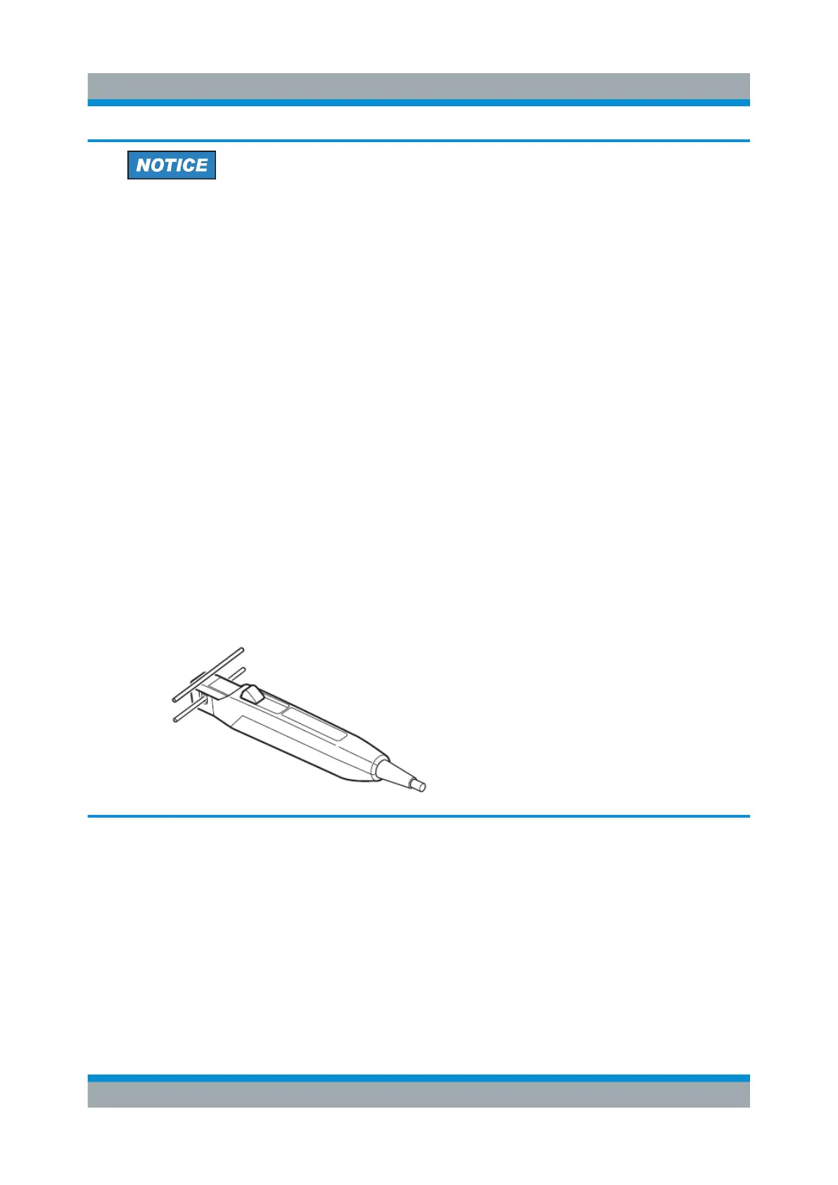
●
Do not place any unclamped conductor with an electric current of a fre-
quency of 10 kHz or more near the sensor head. Current flowing in the
conductor nearby may heat up the sensor head and cause its tempera-
ture to rise, leading to damage to the sensor. For example, when one
side of a go-and-return conductor is clamped and the other side is also
placed near the sensor head as shown in the diagram, even if the elec-
tric current is lower than the consecutive maximum current, electric cur-
rents in both sides will heat up the sensor and raise the temperature,
thereby causing damage to the sensor.
Connecting the Probe to the DUT
 Loading...

