Measuring Procedure
R&S
®
RT-ZC31
21User Manual 1801.4949.02 ─ 01
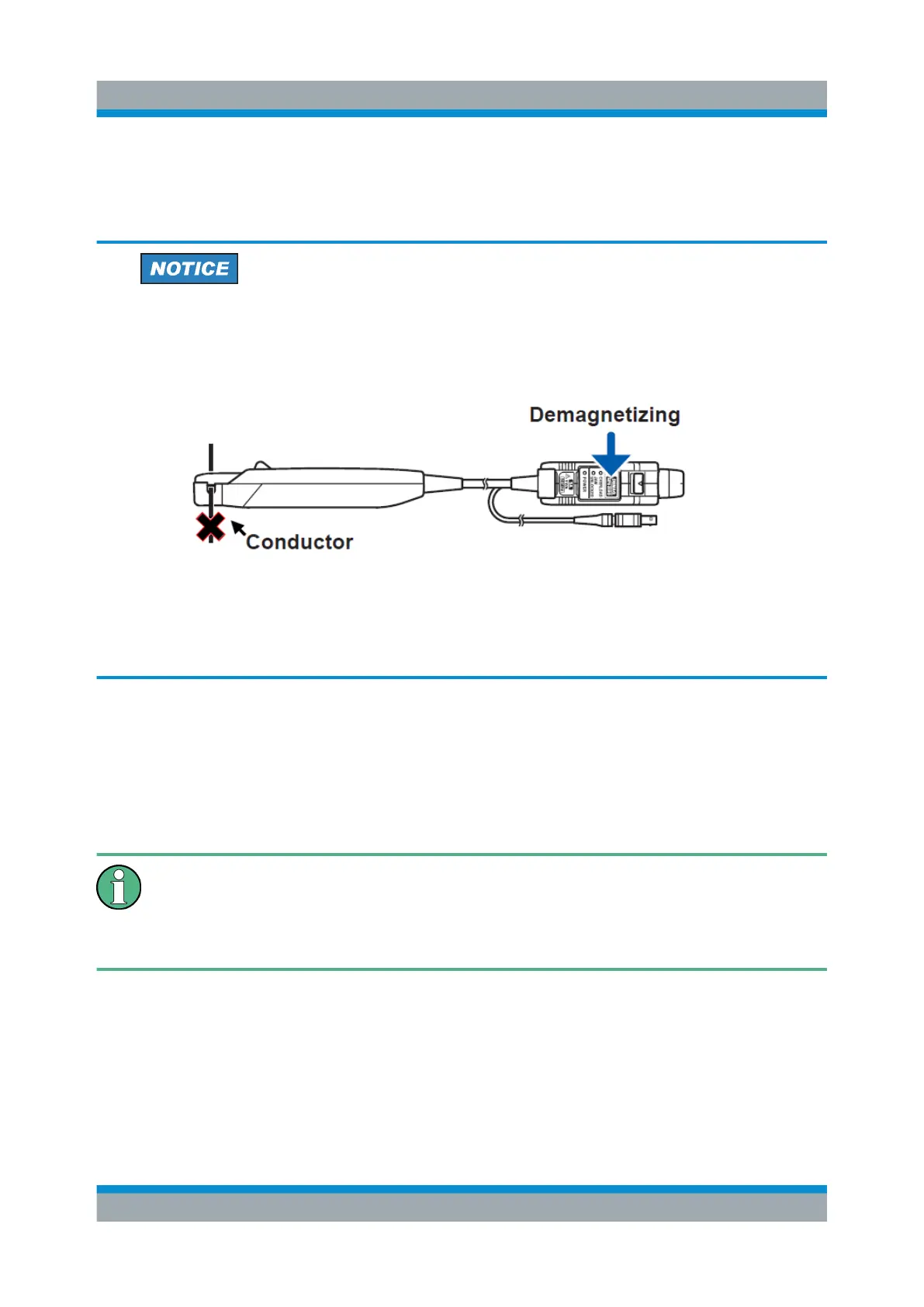
3.2 Demagnetizing and Zero Adjustment
Risk of circuit damage
●
Do not demagnetize while the R&S RT-ZC31 is clamping a conductor to
be measured. Demagnetizing causes current to flow into the conductor,
which may damage parts in the circuit to be measured.
●
Check that the conductor being measured is not clamped when supply-
ing power to the R&S RT-ZC31. When power is turned on, a demagnet-
izing waveform is initially applied to the output. This is intentional in the
design, and not a fault.
During demagnetization (DEMAG / AUTO ZERO LED lit), the device outputs a
demagnetization waveform (which attenuates over time) from its output terminal.
This waveform, which appears on a waveform measuring instrument, may be
asymmetric along the horizontal axis. However, this does not represent a device
malfunction.
Do not move the sensor during demagnetization or automatic zero-adjust-
ment. Disturbance (such as external magnetic fields and temperature
changes) may prevent demagnetization or automatic zeroadjustment from
being completed normally.
1. With the waveform measuring instrument input at ground, adjust the waveform
to the zero position.
2. Connect the R&S RT-ZC31 current probe. Configure the oscilloscope as
described in Chapter 3.1, "Preparing the Measurement", on page 18.
Demagnetizing and Zero Adjustment
 Loading...

