WARNING – SERVICING TO BE CARRIED OUT ONLY BY AN AUTHORISED PERSON
Disconnect from electricity and gas before servicing. Check appliance is safe when you have nished.
25
Adjusting the minimum flame position
First of all, make sure that the appliance is unplugged from
the mains electrical supply and that the gas feed is open.
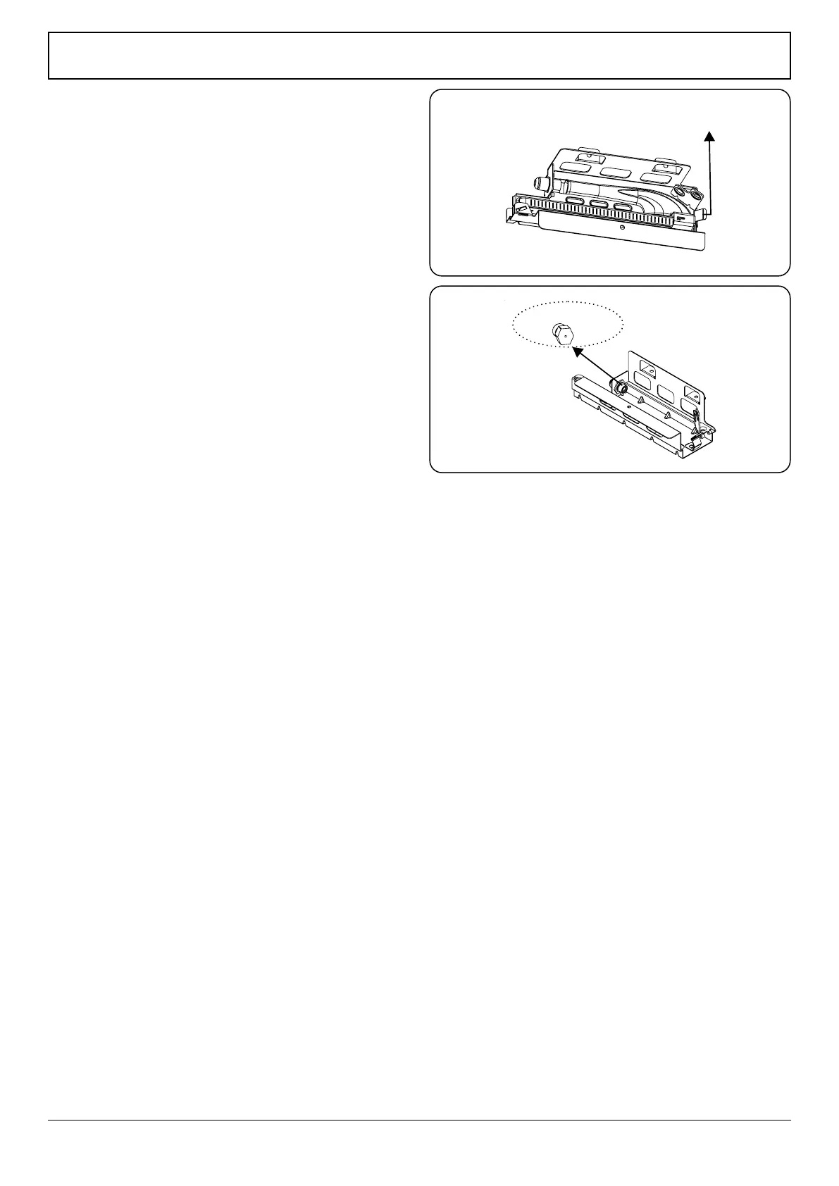
The minimum ame position is adjusted with a at screw
located on the valve. As shown in the gures; for valves with
a ame failure safety device, the screw is located on the side
of the valve spindle and for valves without a ame failure
safety device, the screw is located inside the valve spindle.
To make adjusting the ame position easier, we recommend
that you remove the control panel (and the micro switch if
your model has one) during the alteration. The bypass screw
must be loosened for conversion from LPG to natural gas. For
conversion from natural gas to LPG, the bypass screw must be
tightened.
Determining the minimum flame
position
To determine the minimum position, ignite the burners
and leave them on in the minimum position. Remove the
knobs to gain access to the screws. With the help of a small
screwdriver, fasten or loosen the bypass screw by around 90
degrees. When the ame has a length of at least 4mm, the
gas is well distributed. Make sure that the ame does not
die out when passing from the maximum position to the
minimum position. Create an articial wind with your hand
towards the ame to see if the ames are stable. For the oven
burner, operate the oven burner at the minimum position for
5 minutes, then open and close the oven door 2-3 times to
check the ame stability of the burner.
Changing the gas inlet
For some countries, the gas inlet type can be dierent for
NG/LPG gases. In this case, remove the current connection
components and nuts (if any) and connect the new gas
supply accordingly. In all conditions, all components used
in gas connections should be approved by local and/or
international authorities. In all gas connections, refer to the
“Assembly of gas supply and leakage check”.
Fig. 8.4
Fig. 8.5