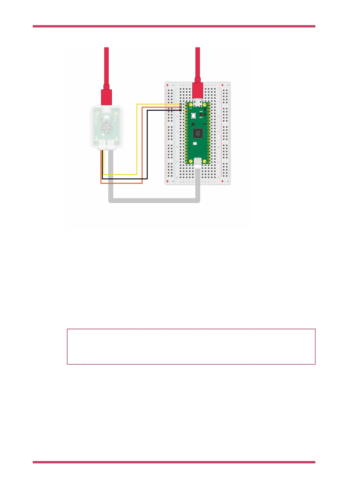
Figure 9. Wiring
between the Debug
Probe (left) and Pico
(right).
To connect Debug Probe to Pico H, connect the following:
•
Debug Probe "D" port to Pico H "DEBUG" SWD JST-SH connector
•
Debug Probe "U" port, with the three-pin JST-SH connector to 0.1-inch header (male):
◦
Debug Probe RX connected to Pico H TX pin
◦
Debug Probe TX connected to Pico H RX pin
◦
Debug Probe GND connected to Pico H GND pin
Then, connect two USB cables: one from your computer to the microUSB port on Debug Probe and another from your
computer to the microUSB port on Pico.
NOTE
If you have a non-H Pico, Pico 2 or Pico W (without a JST-SH connector) you can still connect it to a Debug Probe.
Solder a male connector to the SWCLK, GND, and SWDIO header pins on the board. Using the alternate 3-pin JST-SH
connector to 0.1-inch header (female) cable included with the Debug Probe, connect to the Debug Probe "D" port.
Connect SWCLK, GND, and SWDIO on the Pico or Pico W to the SC, GND, and SD pins on the Debug Probe, respectively.
The wiring loom between Pico and the Debug Probe is shown in Figure 8.
Debug with a second Pico or Pico 2
One Pico or Pico 2 can reprogram and debug another using the debugprobe firmware, which transforms the Pico or Pico 2
into a USB → SWD and UART bridge.
Getting started with Raspberry Pi Pico-series
Debug with a second Pico or Pico 2 18