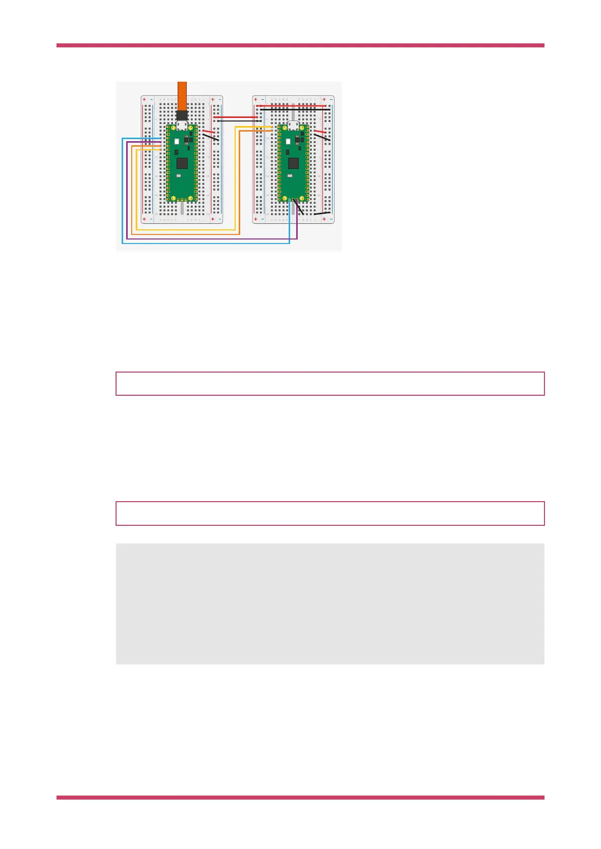
Figure 10. Wiring
between Pico A (left)
and Pico B (right) with
Pico A acting as a
debugger and Pico B
as a system under
test. You must
connect at least the
ground and the two
SWD wires. Connect
the UART serial port to
provide access to the
UART serial output of
Pico B. You can also
bridge the power
supply to power both
boards with one USB
cable. For more
information, see
debugprobe wiring.
Install debugprobe
You can download a UF2 binary of debugprobe from the Pico-series documentation.
Boot the debugger Pico or Pico 2 with the BOOTSEL button pressed. Copy debugprobe_on_pico.uf2 onto the device to begin
debugging.
NOTE
Use debugprobe_on_pico.uf2 to use a Pico for debugging. Use debugprobe.uf2 for the Debug Probe accessory hardware.
Build debugprobe
Alternatively, you can build debugprobe using the following instructions:
These build instructions assume you are running on Linux, and have installed the SDK.
NOTE
These instructions are for Pico; replace the -DPICO_BOARD=pico with -DPICO_BOARD=pico2 for Pico 2
$ cd ~/pico
$ git clone https://github.com/raspberrypi/debugprobe.git
$ cd debugprobe
$ git submodule update --init
$ mkdir build
$ cd build
$ export PICO_SDK_PATH=../../pico-sdk
$ cmake -DDEBUG_ON_PICO=ON -DPICO_BOARD=pico ..
$ make -j4
Boot the debugger Pico or Pico 2 with the BOOTSEL button pressed. Copy debugprobe.uf2 onto the device to begin
debugging.
debugprobe wiring
Getting started with Raspberry Pi Pico-series
debugprobe wiring 19