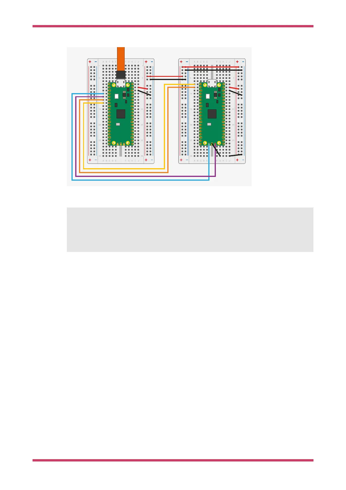
Figure 11. Wiring
between Pico A (left)
and Pico B (right),
configuring Pico A as
a debugger.
The wiring loom between the two Pico boards is shown in Figure 11.
Pico A GND -> Pico B GND
Pico A GP2 -> Pico B SWCLK
Pico A GP3 -> Pico B SWDIO
Pico A GP4/UART1 TX -> Pico B GP1/UART0 RX
Pico A GP5/UART1 RX -> Pico B GP0/UART0 TX
The minimum set of connections required to load and run code via OpenOCD is GND, SWCLK and SWDIO. Connect the UART
wires to communicate with Pico B’s UART serial port through Pico A’s USB connection. You can also use the UART
wires to talk to any other UART serial device, such as the boot console on a Raspberry Pi.
To power Pico A with Pico B, connect the following pins:
•
When using USB in device mode, or not at all, connect VSYS to VSYS
•
When acting as a USB Host, connect VBUS to VBUS to provide 5V on the USB connector.
Debug Probe interfaces
Both the Debug Probe and any Pico-serires device running debugprobe are composite devices with two USB interfaces:
1. A class-compliant CDC UART (serial port), so it works on Windows out of the box.
2. A vendor-specific interface for SWD probe data conforming to CMSIS-DAP v2.
Use the UART
Linux
To use the UART connection on Linux, run the following command:
Getting started with Raspberry Pi Pico-series
Debug Probe interfaces 20
 Loading...