INSTRUCTION, USE AND
MAINTENANCE MANUAL
EN
Page 43 of 91
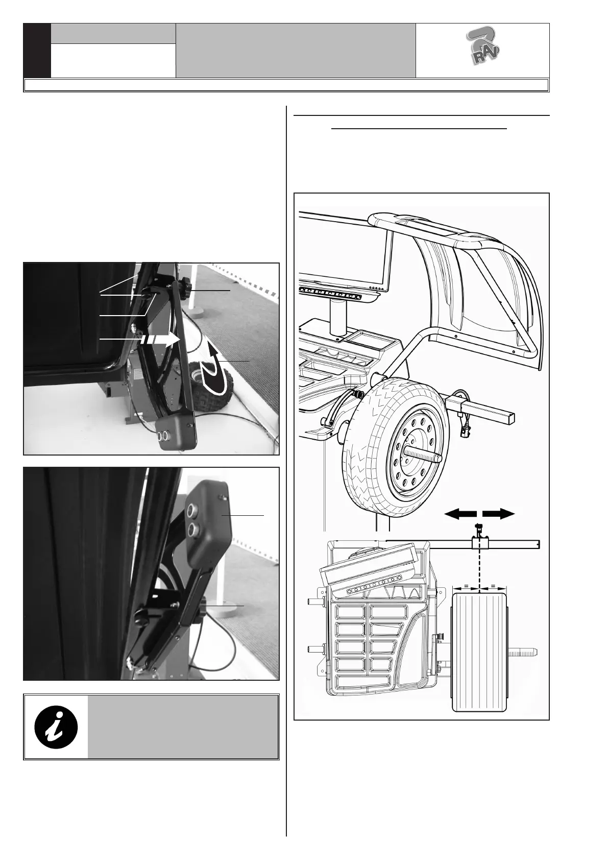
For what concerns exceptionally large wheels, sensor
support may be moved outside the loading space of
the same wheel, so that it can be easily mounted onto
the chuck:
- slacken the handwheels (Fig. 40 ref. 1) fixed to the
protection guard’s tubular and open sensor support
(Fig. 40 ref. 2) by making it slide in the slot (Fig. 40
ref. 3).
- slacken handwheel (Fig. 40 ref. 4)and raise sensor
support (Fig. 40 ref. 5) then move it to the position
required, as indicated in Fig. 41 ref. 1.
At the end tighten the handwheel (Fig. 41 ref. 2).
1
Fig. 40
4
3
2
5
Fig. 41
1
2
IF ACTIVATED, EACH TIME THAT
THE WHEEL PROTECTION GUARD
IS LOWERED, THE DEVICE DE-
TECTS AUTOMATICALLY THE DI-
MENSION OF THE WHEEL WIDTH.
12.4 Correct positioning of ultrasound Run-
out detection device (optional)
To make sure that the rim/tyre “Run-out” detection is
correct, place the device as shown in Fig._42: place
the measurement sensor so that it is turned towards
tyre centre line.
Fig._42
1297-M058-00
G3.150 - GP3.150 - G3.150S - GP3.150S - G3.150WS - GP3.150WS - G3.150WSPLUS - GP3.150WSPLUS - G3.150SA - G3.150WSA
RAVAGLIOLI S.p.A.
 Loading...