EN
Page 16 of 91
INSTRUCTION, USE AND
MAINTENANCE MANUAL
• Execute 4 holes with 10 mm diameter on the floor
by the holes on the bottom floor;
• insert the small blocks (excluded from supply) into
the holes;
• fix the machine to the ground with 4 M8x80 mm
screws (excluded from supply) (Fig. 4 ref. 1) (or
with 4 8x80 mm stud bolts (excluded from supply)).
Tighten the screws with an approximate tightening
torque of 70 Nm.
9.2 Assembly procedures
9.2.1 Fitting the chuck on the flange
For models with threaded chuck
Screw the chuck with an Allen wrench (Fig. 5 ref. 1)
on the flange (Fig. 5 ref. 2).
Fig. 5
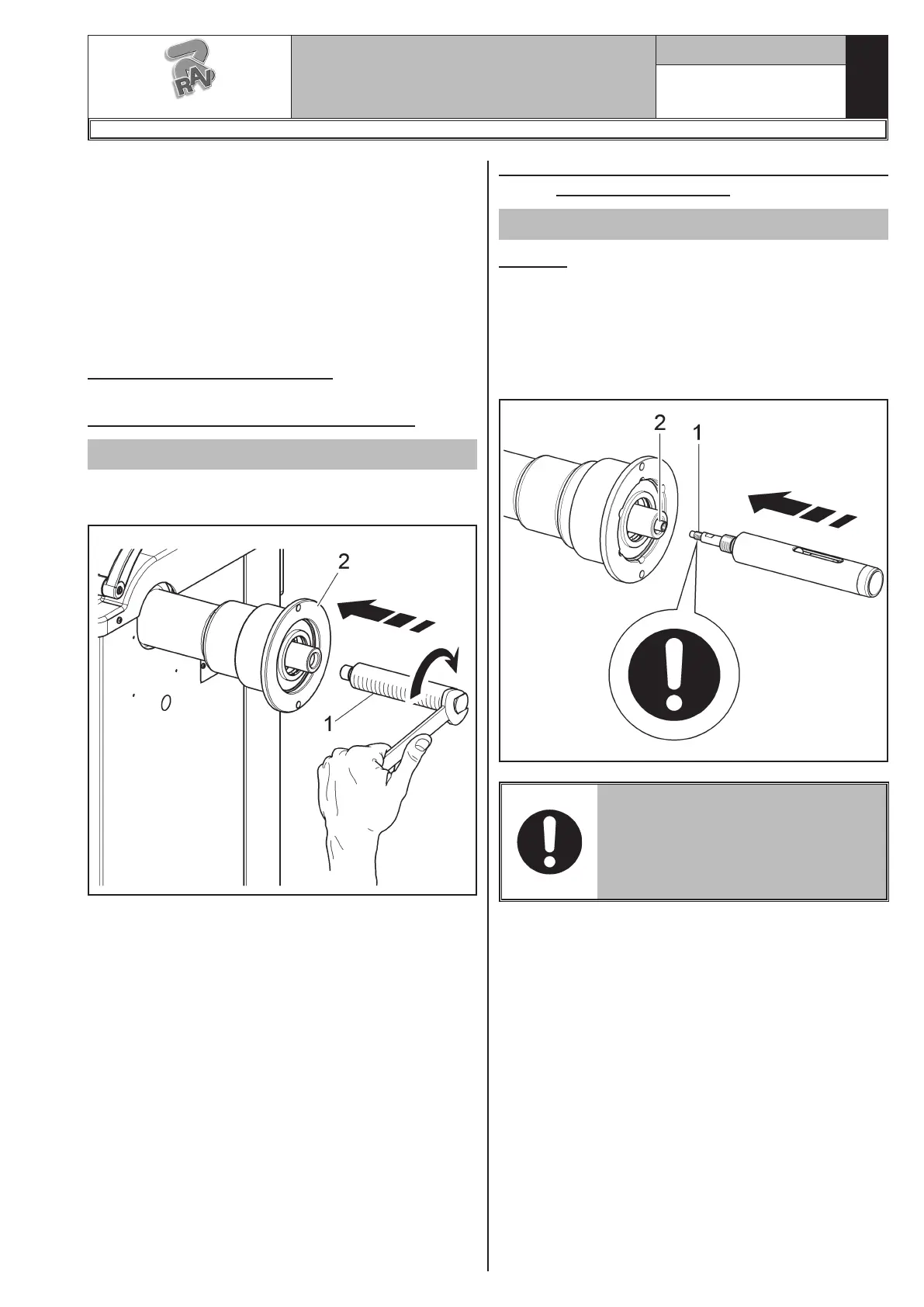
9.2.2 Fitting and removal of the pneumatic
chuck on the flange
On models with pneumatic chuck
FITTING
1. After making power and air connections switch on
the machine (the pneumatic chuck always opens
when the machine is switched on).
2. Switch the machine off by using the main switch
(Fig. 27 ref. 1). Couple tyre inner rod (Fig. 6 ref.
1) with flange inner rod (Fig. 6 ref. 2) (see Fig. 6).
Fig. 6
FOR PNEUMATIC SHAFT KIT
FITTING (FIG. 6 REF. 1) USE ME-
DIUM RESISTANCE LOCTITE 242
THREADLOCKERS OR EQUIVA-
LENT ONLY ON M10 THREAD AND
TIGHTEN TO 30NM.
G3.150 - GP3.150 - G3.150S - GP3.150S - G3.150WS - GP3.150WS - G3.150WSPLUS - GP3.150WSPLUS - G3.150SA - G3.150WSA
RAVAGLIOLI S.p.A.
1297-M058-00
 Loading...