Manual No. 016-0230-014 65
UltraGlide
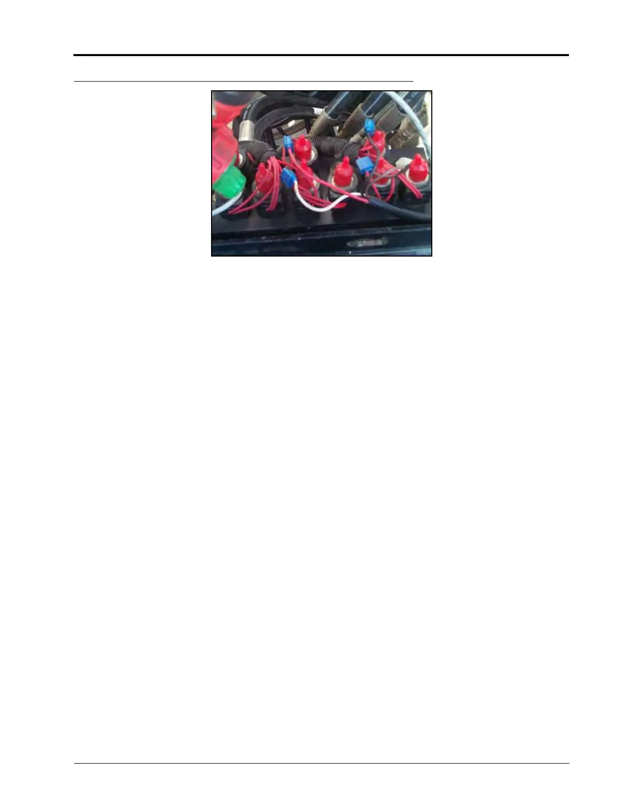
FIGURE 16. Machine’s Boom Function Coils
11. Locate the machine’s boom function coils on the machine’s hydraulic valve.
12. Locate the left tilt up coil.
13. Determine which wire feeding into the coil receives the signal from the switches in the cab by pressing the
switch and using a test light or multi-meter to detect +12 volts.
14. Locate the Left Solenoid Sense Up connector on the AutoBoom harness cable (P/N 115-0230-045).
15. Use a 16-18 gauge scotch lock parallel splice connector (p/N 405-2001-079) to connect the left tilt up coil
wire to the Left Solenoid Sense Up connector.
16. Locate the left tilt down coil.
17. Determine which wire feeding into the coil receives the signal from the switches in the cab by pressing the
switch and using a test light or multi-meter to detect +12 volts.
18. Locate the Left Solenoid Sense Down connector on the AutoBoom harness cable (P/N 115-0230-045).
19. Use a 16-18 gauge scotch lock parallel splice connector (P/N 405-2001-079) to connect the left tilt down
coil wire to the Left Solenoid Sense Down connector.
20. Repeat the steps above to connect the right tilt up and down coils to the Right Solenoid Sense Up and
Down connectors on the AutoBoom harness cable.
Connect the Harness Cable to the Sensors
1. Locate the Center Sensor connector on the AutoBoom harness cable.
2. Connect the Center Sensor connector to the installed center sensor (P/N 063-0130-018).
3. Locate the Left Outer Sensor connector on the AutoBoom harness cable.
4. Connect the Left Outer Sensor connector to the installed left sensor cable (P/N 115-0171-527).
5. Locate the Right Outer Sensor connector on the AutoBoom harness cable.
6. Connect the Right Outer Sensor connector to the installed right sensor cable.
7. If optional inner boom sensors are installed, repeat the steps above to connect the inner sensors.
Connect the Harness Cable to the Implement Extension Tee -
Gen II Cable Only
1. Route the harness cable (P/N 115-0230-085) toward the implement extension tee cable.
2. Connect the harness cable to the To Node connector.
3. Remove the terminator from the machine’s chassis harness or the standalone console harness.
 Loading...

